Product Demo Video
Water Immersion Ultrasonic Imaging Automatic Detection System
1 Equipment Overview
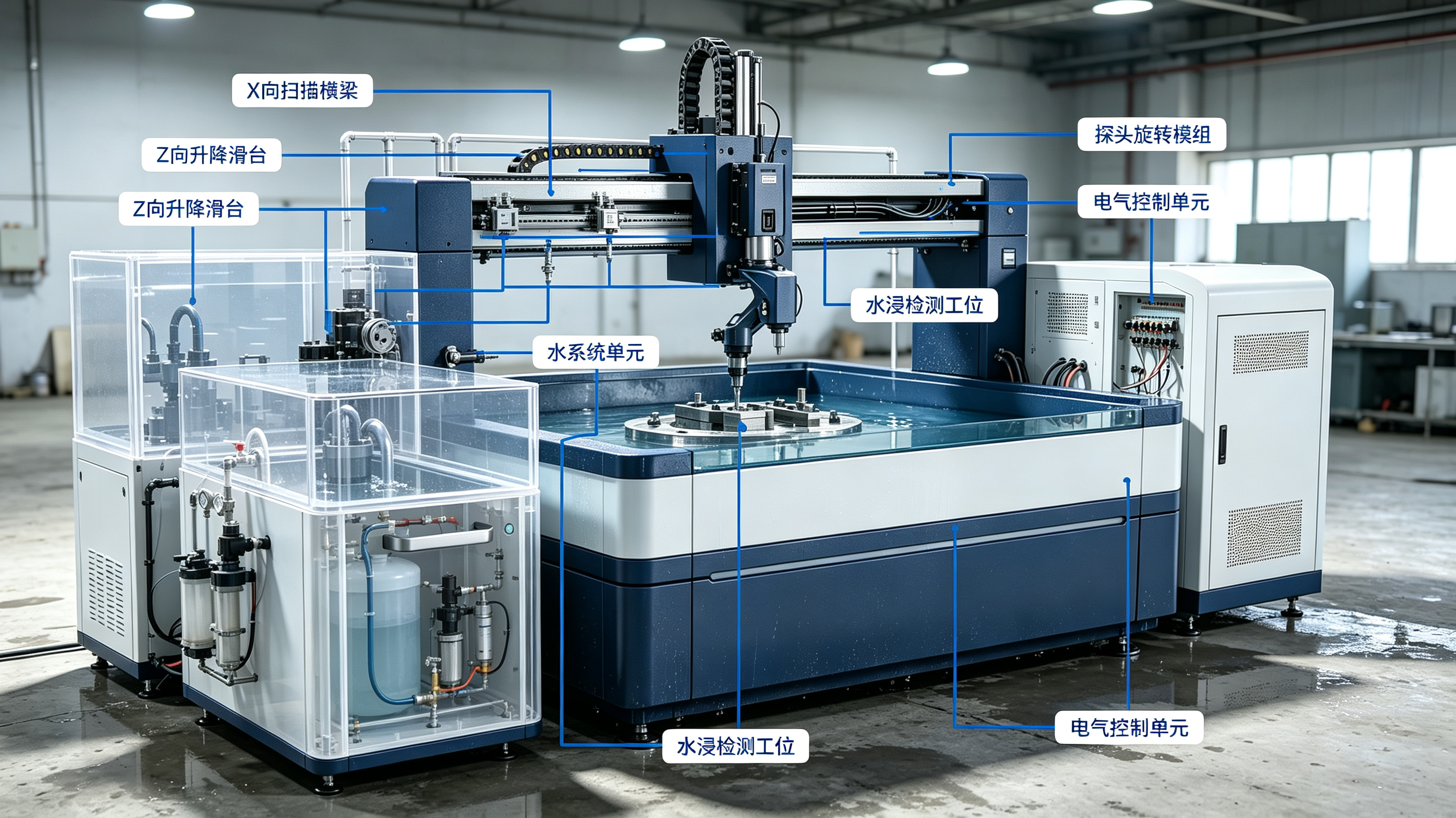
The HS-D100 Water-Immersion Ultrasonic Imaging Automatic Inspection System is a high-precision, fully automatic non-destructive testing (NDT) system. Using purified water as the acoustic coupling medium, and equipped with a multi-axis linkage scanning mechanism and A/B/C/D ultrasonic imaging algorithms, it can reliably identify a wide range of subtle internal defects in metallic components, composite materials, semiconductor materials, and precision-welded structures, including delamination, porosity, cracks, inclusions, cold welding, and interfacial debonding. Compared with manual contact testing, this system overcomes the problems of large human judgment deviations, slow inspection rhythm, and poor result repeatability. It transforms the inspection process into a complete closed loop featuring automated execution, visualized imaging, digital data retention, and standardized result determination, and can cover the quality inspection requirements of all stages of high-end manufacturing. It is suitable for industrial NDT quality control, incoming material inspection, finished-product screening, and scientific research analysis.
2 Core Technical Parameters
The core technical parameters of the HS-D100 system are listed in the table below:
Parameter Category | Parameter Name | Technical Specification |
Ultrasonic inspection parameters | Ultrasonic frequency range | 0.5 MHz – 20 MHz (adaptable for switching between high- and low-frequency transducers) |
| Imaging modes | Full-field A-scan, B-scan, C-scan, D-scan, and F-scan imaging |
| Defect detection resolution | 0.05 mm lateral, 0.1 mm longitudinal; capable of identifying micron-level subtle defects |
| Inspection thickness range | 0.1 mm – 500 mm (adapts to thin-layer precision components through thick-walled industrial castings) |
| Pulse repetition frequency | 10 Hz – 1000 Hz, continuously adjustable |
| Gain adjustment range | 0 – 120 dB, with fine adjustment in 0.1 dB steps |
Motion control parameters | Motion axis configuration | Standard three-axis (X/Y/Z); optional four-axis/seven-axis linkage and rotary worktable |
| Scan travel | X-axis 1000 mm, Y-axis 800 mm, Z-axis 500 mm |
| Positioning accuracy | ±0.02 mm; repeat positioning accuracy ±0.01 mm |
| Scan speed | 0.1 mm/s – 500 mm/s, steplessly adjustable |
Equipment structural parameters | Water tank dimensions | 1200 mm × 1000 mm × 600 mm (custom sizes available) |
| Equipment overall dimensions | 1800 mm × 1500 mm × 1850 mm |
| Equipment weight | Approx. 850 kg |
Performance parameters | Inspection methods | Full immersion, partial immersion, and water-jet coupling with adaptive switching |
| Data storage formats | BMP, JPG, CSV, and DICOM standard formats, supporting traceability archiving |
| Inspection efficiency | Fully automatic batch scanning of large-area workpieces; 3–5 times more efficient than traditional testing |
Electrical parameters | Working power | AC 220V ±10%, 50 Hz, rated power 1.5 kW |
| Working environment | Temperature 5 °C – 45 °C, humidity 30% – 85%, free from strong electromagnetic interference |
3 Core Application Industries and Scenario Details
The HS-D100 features high-resolution imaging, fully automatic operation, non-damaging inspection of workpieces, and broad adaptability to working conditions. It mainly serves five core industries: new energy, semiconductor precision manufacturing, high-end automotive components, special equipment pressure vessels, and medical devices. Mature application cases ready for immediate production use already exist in each of these industries, as detailed below:
3.1 New Energy Industry
In the new energy sector, inspection targets focus on power batteries, energy storage components, and precision heat-exchange components for new energy vehicles. Such products are mostly multi-layer composite or precision-welded structures. Once interfacial defects, welding defects, or structural misalignment occur internally, the safety, stability, and service life of the product are directly affected. This system can accurately determine the interfacial bonding state and internal hidden defects of components, and can meet the inspection rhythm requirements of batch production lines.
3.1.1 Scenario 1: Inspection of welding defects in water-cooling plates for new energy power batteries
Scenario background: The power battery packs of new energy vehicles continuously generate heat during operation, and the water-cooling plate bears the main heat-dissipation function, maintaining the battery temperature within a set range through water circulation in the internal flow channels. Its welding quality is therefore directly related to heat-dissipation efficiency and overall vehicle safety. Water-cooling plates are mostly formed from aluminum alloy sheets by brazing or diffusion welding. During manufacturing, defects such as cold welding, incomplete fusion, weld-layer porosity, interfacial debonding, and flow-channel blockage are prone to occur. If cold welding or debonding is present, the water-cooling plate may crack and leak under driving vibration, which can induce battery short circuit, fire, or even explosion; flow-channel blockage and internal inclusions can cause uneven heat dissipation, triggering thermal runaway and accelerated life degradation. Traditional methods such as pneumatic pressure testing and visual inspection can only detect surface damage and cannot identify internal hidden welding defects; they also have limited accuracy and low speed, making it difficult to meet the mass-production quality control requirements of new energy vehicles. As industry safety standards continue to rise, 100% inspection of water-cooling plates has become a mandatory requirement.
Equipment application process: For the thin-walled welded structure of aluminum alloy water-cooling plates, the system sets the ultrasonic frequency in the low-to-mid range (3–8 MHz) to balance penetration capability and resolution, and invokes the special detection algorithm for thin-walled components. After the operator places the water-cooling plates to be inspected in sequence on the inspection worktable, the equipment automatically completes positioning and calibration, and uses full water-immersion coupling to drive the three-axis mechanism to perform full-coverage scanning along the flow-channel layout and weld direction. The ultrasound passes through the aluminum alloy base material and weld layer, collecting echo signals from the weld interface point by point. The imaging system distinguishes dense regions from defective regions on this basis, clearly showing the location and area of cold welding, incomplete fusion, porosity, and debonding, while also determining whether the internal flow channels are blocked or contain foreign inclusions. The system is equipped with an industry-specific judgment model that can automatically give a welding qualification rate conclusion and classify defects, distinguishing reworkable workpieces from those to be scrapped. The equipment supports continuous batch operation on the production line, with a detection time of no more than 3 minutes per water-cooling plate. Data is synchronously uploaded to the production system, achieving an integrated chain of production, inspection, and traceability, preventing defective water-cooling plates from entering the final assembly stage, and safeguarding the safe and stable operation of the power battery system at its source.
3.1.2 Scenario 2: Inspection of multi-layer interfacial defects in lithium battery cells
Scenario background: Solid-state and liquid-state lithium battery cells are formed by multi-layer lamination of electrode plates, separators, and electrolyte. During the stacking and packaging processes, hazards such as electrode plate misalignment, separator wrinkles, inter-layer inclusions, interfacial delamination, and internal micro-short circuits are prone to occur. Such defects cannot be revealed by visual inspection or electrical testing. After the cell is installed in service, it may exhibit excessively rapid capacity degradation, local overheating, swelling, or even spontaneous combustion, directly threatening the operational safety of new energy vehicles and energy storage power stations. X-ray inspection carries radiation risks, and manual sampling inspection has low coverage and cannot perform full-batch screening. The industry urgently needs a radiation-free, high-resolution, and automatically executable NDT method. Water-immersion ultrasonic inspection produces no radiation and can accurately resolve multi-layer interfacial defects, making it the preferred quality-control solution for lithium battery cells.
Equipment application process: Given the thin-layer, multi-layer structural characteristics of the cells, the system selects a high-frequency, low-loss probe and optimizes sound velocity compensation parameters to suppress signal crosstalk caused by multiple interfaces. The packaged cell is fixed at the inspection station, the equipment automatically injects water to establish coupling, and then performs high-precision, low-speed scanning to inspect the entire cell layer by layer. Using T-scan multilayer imaging technology, the acoustic wave penetrates the composite structure and analyzes the bonding of the electrode plates, separator, and packaging layer layer by layer, accurately identifying electrode plate offset, separator wrinkles, inter-layer bubbles, interfacial debonding, and internal tiny foreign objects. At the same time, the uniformity of material density is assessed based on sound velocity fluctuation data to determine whether cell consistency meets the standard. The system outputs multi-layer imaging maps in real time, displaying defect distribution layer by layer and automatically removing nonconforming products. The entire process is contactless, radiation-free, and non-damaging to the cell, without changing its electrochemical performance. After inspection, the equipment automatically drains the water and dries the station, allowing continuous connection with the production line. It can inspect thousands of cells per day, meeting the quality-control requirements of large-scale mass production of power batteries and helping to improve product consistency and safety.
3.2 Semiconductor Precision Manufacturing Industry
Semiconductor wafers, TSV through-silicon vias, precision packaged devices, and ceramic substrates generally feature ultra-thin, high-precision, and highly integrated characteristics. Internal micron-level defects are sufficient to cause chip failure or package scrap, so the detection resolution must reach the micron level. The ultra-high-resolution imaging capability of this system can undertake NDT tasks for high-end precision semiconductor components.
3.2.1 Scenario 1: Inspection of TSV through-silicon via packaging defects
Scenario background: TSV through-silicon vias are a key process in three-dimensional packaging of high-end chips, achieving multi-layer stacked interconnection of chips through vias, and are widely used in computing chips, memory chips, and automotive chips. During via etching, metal filling, and bonding packaging, defects such as filling voids, metal delamination, bonding interface debonding, and micro-cracks are prone to occur. Such micron-level defects can cause circuit open circuits, abnormal impedance, and heat-dissipation failure, resulting in chip functional failure and significantly reduced service life. The semiconductor industry has near-zero tolerance for packaging defects. Optical inspection can only observe the surface and cannot see hidden problems inside the vias, while the resolution of conventional ultrasonic equipment is insufficient to meet micron-level requirements, making this a technical bottleneck in high-end chip packaging quality control.
Equipment application process: The HS-D100 switches to ultra-high-precision microscopic ultrasonic inspection mode, configures a 20 MHz high-frequency special-purpose probe, and advances resolution to the micron level to match the tiny structures of through-silicon vias. The packaged chip wafer is fixed on a constant-temperature inspection station to reduce the interference of temperature fluctuation on accuracy. The equipment uses micro water-immersion coupling, precisely controlling the coupling water layer thickness to eliminate the influence of bubbles. The three-axis micron-level positioning system scans point by point along the chip array trajectory, collecting signals individually for each through-silicon via and bonding interface. The algorithm then filters out substrate clutter to identify tiny defects such as filling voids, metal-layer delamination, and interface debonding. The system outputs high-resolution three-dimensional imaging maps, annotating defect coordinates and sizes to achieve precise positioning and quantitative analysis. Inspection data can be directly connected to the MES system of the semiconductor production line, supporting full-process traceability of packaging quality, helping to improve the yield of high-end chip packaging, and meeting the strict quality-control standards of precision manufacturing.
3.2.2 Scenario 2: Inspection of internal porosity and delamination defects in ceramic substrates
Scenario background: Ceramic substrates bear the dual functions of heat dissipation and support in power semiconductors and LED chips, and feature good thermal conductivity, high insulation strength, and high-temperature resistance. After entering the sintering, coating, and metallization processes, the substrate is prone to generating internal micro-pores, inter-layer delamination, material non-uniformity, and edge micro-cracks. Porosity weakens heat-conduction capability, causing poor chip heat dissipation or even high-temperature burnout; delamination can cause metal film detachment and insulation failure, resulting in circuit short circuits. Ceramic substrates are only 0.2–2 mm thick, and defect sizes are extremely small. Conventional inspection equipment easily misses defects and finds it difficult to complete full-area quantitative assessment, thereby affecting the stability and reliability of semiconductor devices.
Equipment application process: In view of the characteristics of ultra-thin ceramic substrates, the system has made targeted optimizations to the ultrasonic near-field detection algorithm and keeps gain fluctuation at an extremely low level to suit thin-layer materials. The operator batches and clamps the substrates on a vacuum adsorption fixture to prevent workpiece displacement from affecting accuracy. The equipment then automatically establishes water-immersion coupling and operates in a high-speed, high-precision full-area scanning mode. High-frequency ultrasound penetrates the ultra-thin substrate, capturing echo differences caused by internal tiny defects. Through C-scan imaging, the distribution of porosity, delamination regions, and crack directions is fully presented, and the number of defects, pore diameters, and area proportions are automatically counted. The system determines product grade according to semiconductor industry substrate quality-control standards and screens out nonconforming substrates. The entire inspection process does not damage workpieces and produces no dust, with a relatively fast rhythm, matching the inspection requirements of large-scale substrate production and helping to maintain stable quality of packaging substrates.
3.3 High-End Automotive Components Industry
Chassis components, precision-welded shaft sleeves, brake components, and new energy vehicle electronic control housings among other high-end automotive components generally have very high requirements for structural strength and fatigue resistance. If defects are hidden internally, they may lead to road safety accidents. This system can perform NDT of such precision components in an automated and standardized manner.
3.3.1 Scenario 1: Inspection of internal defects in aluminum alloy chassis forgings
Scenario background: Chassis components such as control arms and steering knuckles of new energy vehicles and high-end passenger cars mostly use aluminum alloy forgings, achieving lightweight while ensuring structural strength, and serve as an important basis for driving stability. During forging and heat treatment, internal defects such as shrinkage cavities, porosity, forging cracks, and inclusions are prone to occur. Such defects are hidden inside the component and often show no obvious signs under static conditions; once the vehicle experiences bumps or heavy loads, the defects expand rapidly, causing chassis component fracture and loss of vehicle control, and leading to major traffic accidents. Manual ultrasonic testing has low efficiency and large judgment deviations, making it difficult to match the batch quality-control requirements of automotive components. The industry therefore needs automated high-precision equipment to complete full-batch screening.
Equipment application process: Based on the material characteristics of aluminum alloy forgings, the system sets the ultrasonic frequency at 5–10 MHz and optimizes metal sound velocity compensation parameters to improve the identification capability of internal defects. The forged chassis components are fixed with flexible fixtures to accommodate the clamping requirements of irregularly shaped parts. The equipment then starts a fully automatic scanning program, with three-axis linkage covering all key load-bearing regions of the forging, and full water-immersion coupling to ensure stable signals. During scanning, echo signals are collected in real time, and the imaging algorithm filters out material clutter to accurately identify shrinkage cavities, porosity, micro-cracks, and impurity inclusions, giving the distribution location and size of defects. The system automatically compares against automotive components industry quality-control standards, determines whether the workpiece is qualified, and generates a standardized inspection report. The equipment can operate in continuous batch mode 24 hours a day with good stability, significantly reducing human judgment deviations, preventing defective chassis components from entering the assembly stage, and ensuring vehicle driving safety.
3.3.2 Scenario 2: Inspection of brazing interface bonding quality of automotive shaft sleeves
Scenario background: Shaft sleeves in transmission and suspension systems are usually made by metal brazing composite processes, and their wear resistance and fatigue resistance mainly depend on the bonding rate and density of the brazing interface. If fluctuation occurs in the brazing process, problems such as cold welding, debonding, solder voids, or low bonding rate form on the interface. Under long-term operation, the shaft sleeve subsequently develops loosening, wear, abnormal noise, or even failure, affecting transmission accuracy and driving stability. Previous inspection methods could not quantify the brazing bonding rate and could only rely on destructive sampling inspection for verification, resulting in large workpiece loss, low inspection efficiency, and the inability to achieve full-volume quality control.
Equipment application process: The system invokes the brazing-specific detection algorithm to match the acoustic characteristics of the metal brazing interface and sets corresponding frequency and gain parameters. The finished shaft sleeves are sequentially clamped on the rotary fixture. The equipment drives the workpiece to rotate at a uniform speed, and coordinates with the probe to scan along the axial direction, thereby achieving 360° no-dead-angle coverage of the annular brazing interface. The water-immersion coupling medium ensures uniform and stable ultrasonic signals. The equipment distinguishes dense brazing regions from defective regions based on echo differences, automatically calculates the interface bonding rate, void area, and debonding range, and makes a quantitative assessment of welding quality. After inspection, the system automatically classifies products into premium products, qualified products, rework products, and scrap products. As this is non-destructive inspection, workpieces are not consumed, and 100% full inspection can be performed; the quantitative data also provides a basis for brazing process improvement, helping to enhance the quality of shaft sleeve products.
3.4 Special Equipment Pressure Vessel Industry
Special equipment such as high-pressure storage tanks, heat-exchange vessels, and industrial pressure pipelines operate under high-pressure, high-temperature, and corrosive conditions for long periods. Internal weld and plate defects may cause explosions or leaks. The state mandates regular NDT and factory full inspection of special equipment. This system can meet the high-precision testing needs of such equipment.
3.4.1 Scenario 1: Inspection of internal defects in welds of high-pressure pressure vessels
Scenario background: The chemical, energy, and metallurgical industries widely use industrial high-pressure pressure vessels. Such equipment operates under high-pressure sealed conditions for long periods, and the welds at the cylinder and head are weak points in the structure. During welding, defects such as incomplete penetration, incomplete fusion, weld porosity, welding cracks, and slag inclusions are prone to occur; under the repeated action of long-term high-pressure loads, the defects continue to expand, easily causing vessel leakage or even explosion. According to special equipment safety regulations, pressure vessels must undergo 100% NDT before leaving the factory and must receive regular re-inspection during service. Manual testing carries strong randomness, the data is difficult to trace, and the accuracy is limited, making it difficult to meet the requirements of special equipment safety specifications.
Equipment application process: Considering the large wall thickness of pressure vessel welds, the system adopts low-frequency, high-penetration ultrasonic frequencies (1–5 MHz), ensuring that the acoustic wave can pass through thick-walled plates while retaining the necessary defect resolution capability. After the cylinder is stably placed at the inspection station, the system automatically identifies the weld direction and generates a scan path, eliminating the need for manual line marking and positioning. Scanning is performed with partial water immersion, operating directionally only on the weld region to avoid interference from non-inspection areas, while collecting internal weld signals in real time. With combined C-scan and B-scan imaging, the location, depth, and size of various defects are clearly displayed. The system is built with special equipment NDT industry standards, can automatically determine whether defects exceed limit values, issue standardized inspection reports, and support long-term data archiving for traceability. The equipment can adapt to pressure vessels of different specifications, has a high degree of automation, can significantly reduce manual inspection costs, and meets the compliance requirements for factory inspection and periodic re-inspection.
3.4.2 Scenario 2: Inspection of corrosion and internal defects in industrial thick-walled pipelines
Scenario background: Thick-walled pipelines used in chemical and oil-and-gas transportation are in long-term contact with corrosive media, and the pipe wall is prone to uniform corrosion, local pitting, internal cracks, and uneven wall-thickness reduction. Corrosion exceeding limits or crack expansion can cause medium leakage and pipeline rupture, resulting in environmental pollution and production safety accidents. Conventional wall-thickness inspection can only measure point by point and cannot cover the entire pipe wall. Local hidden corrosion is difficult to detect, with low inspection coverage and incomplete hazard investigation.
Equipment application process: The system is equipped with a pipeline-specific rotary scanning fixture to meet the full-area inspection needs of circular pipelines, and sets ultrasonic parameters according to the characteristics of thick-walled pipelines and enables the wall-thickness dynamic monitoring algorithm. After the pipeline is clamped on the fixture, the equipment drives it to rotate at a uniform speed while the probe scans along the axial direction, so the inner wall, outer wall, and middle layer of the pipe wall can all be covered. The system calculates the real-time wall thickness of the pipe based on ultrasonic echoes, compares it against the standard wall thickness to determine the degree of corrosion thinning, and identifies internal fatigue cracks, interlayers, porosity, and other defects. It then automatically generates a wall-thickness distribution cloud map and defect distribution map, annotating severely corroded regions and defect locations, providing a data basis for pipeline repair, replacement, and maintenance. The inspection has comprehensive coverage without blind spots, and the data is traceable, helping to solve the missed-detection problem of traditional pipeline inspection and ensuring the long-term safe operation of industrial pipelines.
3.5 Medical Device Industry
Medical implants and precision medical devices have very high requirements for safety and biocompatibility. Even a tiny internal defect may directly endanger the life and health of patients. This system can perform high-precision NDT of medical components, meeting the strict quality-control standards of the medical industry.
3.5.1 Scenario 1: Inspection of internal defects in titanium alloy orthopedic implants
Scenario background: Orthopedic titanium alloy bone screws, bone plates, and artificial joints must remain in the human body for long periods and bear motion loads. If they contain micro-cracks, porosity, or inclusions, fracture, loosening, and inflammatory stimulation may occur after implantation, seriously affecting the patient's rehabilitation outcome and health. The medical industry has zero tolerance for implant defects. Products must undergo 100% NDT, and the inspection accuracy and cleanliness requirements are far higher than for ordinary industrial products. Contact testing not only easily contaminates the workpiece but also has insufficient accuracy, making it difficult to meet the quality-control requirements of medical products.
Equipment application process: Clean water-immersion coupling is used throughout the process without introducing chemical couplants, meeting the cleanliness requirements of medical products. In view of the precise structure and relatively small size of titanium alloy implants, the system sets high-frequency, high-precision ultrasonic parameters and invokes the special scanning algorithm for tiny components. After the sterilized implant is fixed on a sterile fixture, the equipment automatically completes full-area scanning, accurately finding internal micron-level porosity, micro-cracks, and material inclusions, while assessing the bonding density between the surface coating and the substrate. The system outputs high-definition imaging reports, based on which it determines whether the product meets the safety standards for medical implants and screens out nonconforming products. The entire inspection is contactless, non-damaging, and contamination-free, does not damage the surface accuracy or biocompatibility of the workpiece, and can meet the strict inspection requirements for medical device factory release, ensuring clinical use safety.
3.5.2 Scenario 2: Weld quality inspection of precision-welded medical instruments
Scenario background: Medical minimally invasive surgical instruments and stainless steel precision tube fittings are mostly formed by precision welding. The density of the weld directly determines the structural strength and corrosion resistance of the instrument. If the weld has cold welding, porosity, or incomplete fusion, the instrument may crack or suffer corrosion leakage under high-temperature disinfection and clinical load conditions, leading to medical infection, surgical failure, and other accidents. Such instruments are small in structure and complex in shape, and conventional inspection equipment is difficult to adapt to micro welds, so a high-resolution NDT solution is needed.
Equipment application process: The system switches to ultra-high-precision micro-scanning mode to adapt to the structure of small, irregularly shaped instruments, and optimizes the signal recognition algorithm for micro welds to filter out structural clutter. After the instrument is fixed on a micro fixture, the weld is scanned point by point with micro water-immersion coupling. The equipment can capture tiny defects inside the micro weld, quantitatively assess weld density and defect size, and output clear weld imaging maps. The product grade is automatically determined by the system according to medical device industry standards, thereby standardizing and automating the welding quality inspection of precision instruments. The whole process is non-destructive and clean, ensuring the quality and safety of medical devices and meeting the high-standard quality-control requirements of the medical industry.
4 System Operation Software Overall Functional Architecture
The system operation software is designed on a modular basis, with a clear interface and well-defined functional partitions. It comprises ten functional modules including file management, project control, scan execution, image processing, precision measurement, hardware configuration, special inspection, and system settings, covering the full-process operation requirements of NDT. The functions of each menu are described below.
4.1 File Menu Functions
The file menu is the basic operation module of the system, used to manage the entire lifecycle of inspection project files and image files, supporting data creation, storage, export, and printing. It is the main entry point for the retention and traceability of inspection records. Its sub-functions are as follows:
New: Creates a blank inspection project file, resetting all scan parameters, image data, and operation records to zero, for starting inspection tasks on new workpieces, preventing data from different workpieces from being mixed up.
Open: Reads inspection projects and image files previously saved on the machine, allowing past scan data, defect images, and inspection parameters to be reviewed again, facilitating data review and secondary analysis.
Save: Immediately writes the project parameters and image data currently being edited or scanned into the original file and overwrites it, preserving inspection progress at any time and avoiding data loss.
Save As: Writes the current inspection project and image data under a new name and path, leaving the original file unaffected, suitable for data classification, retention, and version archiving of multiple workpieces in the same batch.
Save Image: Exports the A-scan and C-scan images produced by scanning separately, which can be saved locally in image format for directly preparing inspection reports, archiving data, or acceptance presentation.
Print: Prints inspection project reports, scan images, and defect data in a single operation, directly producing paper inspection reports for enterprise quality inspection archiving, customer acceptance delivery, and industry audits.
Options: The dedicated settings of the file module, used to adjust basic parameters such as file save path, default storage format, print template, and auto-save rules.
Exit: Safely closes the current inspection project or exits the software. Before exiting, it prompts to save data to prevent data loss caused by misoperation.
4.2 Start Menu Functions
The start menu is the core control module of the system, responsible for project-level management, equipment control, pre-selection of scan modes, and pre-operations such as basic image adjustment and data correction, from which inspection tasks are initiated. Its specific functions are as follows:
Project file operations: Centralizes the creation, opening, import, and export of projects for batch management of inspection projects and quick access.
Equipment control: Performs pre-operations such as power-on self-test, pre-startup of motion axes, probe status check, and system hardware initialization, ensuring the equipment is in a normal operating state after power-on.
Scan mode selection: Allows pre-selection of one of six modes — plane, cylinder, disk, frustum, sector, and sector ring — corresponding to the current workpiece form, providing pre-configuration for accurate scanning.
Image zoom: Supports image enlargement, reduction, and adaptive full-screen display, facilitating observation of tiny defect details in local areas of the workpiece and improving the accuracy of defect identification.
Image correction: Corrects image distortion and signal offset caused by slight environmental or equipment deviations during scanning, ensuring clear imaging and accurate data.
4.3 Scan Menu Functions
The scan menu undertakes the core execution functions of the system, covering all stages of scan operations, from scan plan formulation and full-process execution to equipment motion control, point calibration, axis adjustment, and scan status management. The functions are both comprehensive and detailed, and can meet the high-precision scanning requirements of various workpieces. Its sub-functions are as follows:
Define: According to the shape, dimensions, and accuracy requirements of the workpiece, independently set the scan trajectory, scan speed, scan interval, and inspection range, forming a scan plan dedicated to the workpiece.
Execute: Runs the set scan plan, with the system automatically coordinating multi-axis linkage to drive the ultrasonic probe to complete automatic scanning and acquisition over the entire workpiece.
Probe library: Has a built-in standardized probe parameter database, allowing probe model selection and parameter entry, addition, deletion, and modification, facilitating switching between probes of different frequencies and specifications.
Shape scan adaptation: Provides six dedicated scanning functions — plane, cylinder, disk, frustum, sector, and sector ring — enabling one-click matching of the scan mode to the corresponding workpiece, automatically conforming to curved or planar trajectories and eliminating detection blind spots.
Scan status control: Provides four operations — start, pause, stop, and retrace — allowing tasks to be interrupted at any time or progress to be traced back, meeting the needs of workpiece re-inspection and partial re-scanning.
Manual control function: Integrates handle control, precise positioning, and point reset, allowing manual fine adjustment of probe position for precise scanning of local areas and targeted re-verification of defects.
Point reset calibration: Provides actions such as return to origin, return to safe point, transducer-change point positioning, return to disk center, return to X-axis center, return to Y-axis center, and return on shutdown, enabling accurate reset of the equipment axes and ensuring a consistent scan trajectory for each scan.
Calibration function: Comprises fixture-frame calibration, standard-point calibration, maximum-wave acquisition, and equal-spacing maximum-wave calibration, used to accurately calibrate ultrasonic signals and equipment motion accuracy, ensuring reliable inspection data.
Axis control: Performs high-precision adjustments such as A-axis return to zero, A-axis -90° positioning, B-axis return to zero, B-axis horizontal calibration, turntable lifting, and turntable lowering, meeting the multi-angle scanning requirements of irregularly shaped workpieces.
4.4 Image Menu Functions
The image menu is oriented toward post-processing, display optimization, and data analysis of scanning imaging. It can comprehensively improve the presentation of inspection images and extract key data from them, providing a visual basis for defect analysis. Its functions are as follows:
Basic image settings: Allows switching of image types, adjustment of imaging levels, and customization of image parameters to suit the imaging display needs of various defects.
Image access: Allows manual saving of scan images and loading of historical images, facilitating comparative analysis and data review of multiple batches of images.
Image visual optimization: Has a built-in color palette function, allowing customization of color scheme, contrast, and brightness to amplify the visual difference between defective and normal regions, making it easy to quickly locate defects.
C-scan special settings: Allows configuration of C-scan imaging parameters, setting of background and background display switches, and adjustment of C-scan row/column display, for fine optimization of full-area imaging effects in support of full-area defect analysis.
Auxiliary display function: Allows display of a ruler, adjustment of scale, and customization of colors, for accurately reading the size and position coordinates of defects in images.
Data analysis function: Can open detailed information attached to images, including scan parameters, workpiece information, and acquisition time; it can also generate image histograms, intuitively reflecting the uniformity of internal material and the distribution density of defects in the workpiece.
4.5 Measurement Menu Functions
The measurement menu is the defect precision analysis module, which carries out defect assessment, annotation, and data organization around scan images, converting defects into quantitative results. It is a key stage in the output of quality inspection data. Details are as follows:
Defect assessment: Based on scan image data, the system automatically calculates the size, area, depth, and location of defects, and then determines the defect grade in combination with industry inspection standards, giving a quantitative assessment result.
Annotation: Supports manual annotation of defect location, size, and type using text and lines, clearly marking defective regions for report presentation and problem traceability.
Delete: Can individually delete an erroneous annotation or invalid marker, retaining the valid inspection data.
Clear All: Clears all annotations on the image at once and resets the measurement state, facilitating a new round of analysis.
4.6 CAD Drawing Menu Functions
The CAD drawing menu can be used to draw workpiece outlines, simulate scan trajectories, fit defect region outlines, and draw inspection drawings. The operator can draw the structural outline and defect distribution outline of the workpiece by referencing the scan image, directly forming inspection drawings and defect schematic diagrams. The drawings support saving, export, and printing, meeting the needs of enterprises in drawing archiving, process analysis, and acceptance reporting. It can also be used to optimize scan trajectories, further reducing detection blind spots for irregularly shaped workpieces.
4.7 Ultrasonic Card Menu Functions
The ultrasonic card menu is the core hardware configuration module, responsible for parameter setting, status monitoring, and functional debugging of the ultrasonic acquisition card, directly related to whether ultrasonic signals can be accurately acquired. It can match the ultrasonic card model, adjust signal acquisition parameters, transmit/receive parameters, signal gain and filtering parameters, and perform hardware status self-tests. Operators can customize acquisition parameters according to the workpiece material, thickness, and accuracy requirements, improving signal quality and suppressing clutter, thereby enhancing the sensitivity and accuracy of defect detection. It also has the capability of ultrasonic card hardware fault self-test, feeding back the equipment operating status in real time for convenient maintenance and debugging.
4.8 Options Menu Functions
The options menu handles the global configuration of the system, consisting of two sections — window management and hardware parameters — used to adapt the system to different hardware devices and customize the operating interface. Its functions are as follows:
Window management: Various functional windows can be freely opened, closed, and scaled, including the ultrasonic card monitoring window, motion control window, scan parameter window, data output window, and 3D real-time monitoring window. Through these windows, ultrasonic signal data, equipment motion status, scan progress, and 3D workpiece models can be viewed at any time, keeping the inspection process under visual monitoring.
Hardware parameter settings: Allows customization of mechanical parameters, matching of motion control card types, and selection of acquisition card types. Key parameters such as motion accuracy, acquisition rate, and mechanical limit can be adjusted according to the equipment hardware configuration and inspection requirements, making the system applicable to equipment with different hardware configurations and enhancing compatibility and expansion capability.
4.9 Braze Ratio Menu Functions
The braze ratio menu is a functional module oriented toward special inspection, designed specifically for brazed composite workpieces, and is the core of quality inspection for material welding and brazing processes. The system analyzes the bonding state of the brazing region by collecting ultrasonic reflection signals from the brazing layer, automatically calculates the braze ratio value of the workpiece, and can identify defects such as debonding, cold welding, incomplete brazing, and local voids in the brazing layer, and issue a braze ratio inspection report, providing data support for brazing quality assessment and process improvement. It is commonly used for special inspection and scientific research detection of composite materials and brazed components.
4.10 User Menu Functions
The user menu undertakes the permission management function of the system, and can manage multiple user accounts, divide permission levels, record operation logs, and modify account passwords. The system can establish accounts with different permissions such as administrator, operator, and guest, separating permissions for equipment operation, parameter modification, data export, and report printing, thereby standardizing the equipment use process and preventing non-professionals from causing equipment failure or data loss through misoperation. The operation logs of all users are automatically recorded, and equipment usage is fully traceable, meeting the requirements of standardized management of industrial equipment.
4.11 Tools Menu Functions
The tools menu gathers various tools for operation and maintenance assistance, parameter debugging, and data optimization, including system self-test, parameter backup and recovery, batch data export, batch image processing, equipment precision calibration, log query, and system parameter reset. With it, daily fault self-check, batch saving and reuse of inspection parameters, and rapid organization of large quantities of inspection data can be accomplished, significantly improving the efficiency of equipment operation and maintenance and inspection operations. Tool parameters also support customization to suit the operating habits of different users.
5 General System Operation Workflow
To ensure the standardization and normalization of inspection work, the general operation workflow of this system is as follows. All workpieces are inspected according to this workflow to ensure accurate data and compliant processes:
Equipment power-on self-test: Start the equipment and system software, and perform hardware self-tests on the ultrasonic card, motion control card, axes, and probe to confirm the equipment is operating normally.
Project creation and configuration: Establish an inspection project in the file menu and fill in basic information such as workpiece model, material, and dimensions.
Parameter presetting and debugging: According to the workpiece shape, select the corresponding scan mode in the start menu, and configure hardware parameters such as ultrasonic parameters, scan speed, and inspection accuracy.
Scan plan formulation: Open the scan menu, formulate the scan trajectory for the workpiece, and complete probe calibration, standard-point calibration, and axis reset.
Fully automatic scan execution: After enabling the scan function, the system automatically scans and acquires full-area data of the workpiece, and can pause, stop, or retrace as needed during the process.
Image optimization and analysis: After scanning, use the image menu to improve the imaging effect, view image data and histograms, and complete image preprocessing.
Defect measurement and assessment: Use the measurement menu to annotate defects, measure sizes, and assess defect grades, forming inspection data.
Special inspection analysis: Enable the braze ratio function for brazed workpieces for special inspection, and output braze ratio data.
Data retention and output: Save the project files and inspection images, and print inspection reports or export data as needed, finally completing inspection archiving.
Equipment reset and shutdown: After inspection, return the equipment to the safe point, close the system software, and cut off power, ending all operations.
6 System Maintenance and Safety Specifications
6.1 Core Equipment Maintenance Advantages
The HS-D100 water-immersion ultrasonic imaging automatic inspection system adopts modular design, intelligent operation and maintenance, and a low-loss structure, which can significantly reduce operation and maintenance costs and the probability of failure. Compared with traditional ultrasonic inspection equipment, this system has multiple maintenance advantages and is suitable for long-term continuous mass production at industrial sites:
Modular integrated design for convenient and efficient maintenance: The entire machine integrates the ultrasonic inspection module, motion control module, water circulation module, and industrial control module independently, with no mutual interference between modules and standardized interfaces. In the event of a minor fault, the faulty module can be accurately located without disassembling the entire machine; the module can be inspected, repaired, or replaced individually, significantly shortening maintenance downtime. When an integrated testing device fails, it usually requires whole-machine troubleshooting and disassembly repair, with downtime often lasting several days. The maintenance time for a single fault of this equipment can be controlled within 2 hours, which is conducive to ensuring continuous production-line operation and reducing losses from production stoppage.
Intelligent self-diagnosis and early warning for proactive fault avoidance: The equipment is equipped with an intelligent operation and maintenance monitoring system that can monitor the operating status of the ultrasonic probe, motion motors, water circulation system, power supply system, and signal acquisition system around the clock. Key data such as temperature, rotation speed, signal accuracy, water level, and pressure are collected in real time. The system has a built-in fault early-warning model that can predict hazards such as probe wear, motor stalling, water-path blockage, and signal offset in advance, proactively pop up alerts and push operation and maintenance suggestions, supporting advance maintenance and advance replacement of wearing parts, reducing sudden faults at the source, lowering the failure rate, and extending the service life of the equipment.
Water circulation self-cleaning system to reduce maintenance costs: The equipment is equipped with a closed-loop water circulation, filtration, sterilization, and self-cleaning system, with multiple stages of precision filter elements and an ultraviolet sterilization module built in, which can automatically filter out impurities in the water, inhibit microbial growth, prevent water turbidity, and prevent impurities from adhering to the probe and workpiece, ensuring long-term stability of ultrasonic signals. The system supports automatic sewage discharge and automatic water replacement, eliminating the need for frequent manual cleaning of the water tank or replacement of the water source, thereby reducing maintenance workload. The waterproof and sealed structure has also been upgraded in synchronization, with core electrical and moving components treated for waterproofing and corrosion resistance to avoid water vapor erosion and rust aging, suitable for long-term water-immersion operation with less component wear.
Strong durability of core accessories with extremely low consumption cost: The standard ultrasonic probe of the equipment is an industrial-grade high-wear-resistance model, using imported piezoelectric crystal materials, with anti-attenuation, water-immersion resistance, and long service life, with a service life more than 3 times that of ordinary probes. The motion axes are driven by precision ball screws combined with servo motors, with smooth transmission and very little wear, and will not develop positioning deviations during long-term operation, nor require frequent precision calibration. The entire machine has no large parts that are easily damaged or consumed; only small parts such as filter elements and sealing gaskets need to be replaced periodically. The annual parts consumption cost is less than 30% of that of traditional equipment, showing obvious operation and maintenance economy.
Automatic precision calibration without frequent manual debugging: The equipment has a built-in fully automatic precision calibration program. Before each power-on or daily production, the probe precision, motion positioning, sound velocity parameters, and water level parameters are automatically calibrated and corrected, so long-term use does not require manual adjustment, and the deviations caused by manual calibration are also avoided. The precision of the equipment remains stable during long-term operation, neither drifting nor deviating, reducing manual operation and maintenance operations, lowering the technical threshold for operators, while ensuring the consistency and accuracy of batch inspection data.
Integrated dustproof and anticorrosion protection for complex industrial conditions: The entire machine uses sheet-metal spraying anticorrosion technology, the worktable and moving components use stainless steel rust-proof materials, and the industrial control system is equipped with a dustproof and moisture-proof structure, capable of adapting to complex conditions such as factory dust, humidity, and temperature fluctuations. The equipment has strong anti-interference and anti-aging capabilities, and is not prone to structural damage or circuit failure during long-term continuous operation, with good environmental adaptability, reducing operation and maintenance difficulty and failure probability under harsh conditions.
6.2 Daily Maintenance Specifications
Before power-on each day, check the water tank water level, probe status, and whether the axes operate flexibly, and remove impurities in the water tank to ensure clean coupling water quality.
After each inspection, immediately save the inspection data and wipe off water stains on the equipment table and probe to prevent equipment rust and probe damage.
Periodically use the system's tools menu to perform equipment self-test and parameter calibration to ensure scanning accuracy and stability of signal acquisition.
Probe library parameters should be updated periodically; after switching probes according to inspection requirements, promptly match the hardware parameters to ensure the equipment is properly adapted.
System parameters and inspection data should be backed up periodically to avoid data loss and keep inspection archives complete and traceable.
6.3 Safe Operation Specifications
Operators should read through all functions and operation processes in this manual and hold the corresponding qualification certificate before operating; non-professionals must not operate the equipment in violation of regulations.
During equipment operation, do not touch the motion axes, scanning probe, or workpiece platform to avoid mechanical collision, equipment damage, or personal injury.
Do not arbitrarily modify core system hardware parameters or precision ultrasonic card parameters; parameter adjustment must be performed by professionals according to inspection requirements.
In the event of faults such as abnormal signals, axis stalling, or software errors, immediately stop operation and cut off power for troubleshooting, and must not continue running with the fault.
Strictly follow the permission hierarchy during operation; any behavior of modifying system configuration or deleting historical inspection data beyond one's permission level is prohibited, to ensure system operation safety and data integrity.
7 Common Faults and Solutions
Weak ultrasonic signals and excessive clutter: First check whether the probe is clean and whether the coupling water is pure, then re-calibrate the ultrasonic card parameters, and make corresponding adjustments to signal gain and filtering parameters.
Scan trajectory offset and inaccurate positioning: First perform axis return to zero and center-point reset, then re-calibrate the standard points and fixture frame, and finally calibrate the mechanical motion parameters.
Blurred image imaging and severe distortion: Improve the C-scan parameters and background settings, reset the scan speed and scan interval, and correct the image parameters.
Project files cannot be saved or exported: Check the equipment storage path and remaining storage space, reset the option parameters in the file menu, and then restart the system software.
Hardware devices cannot operate in linkage: Check whether the motion control card and ultrasonic card are connected properly, re-match the hardware parameters, and then restart the equipment self-test.
Spesifikasi
Fitur Utama
- 1. Advanced detection medium and hardware architecture: Adopts purified water as the acoustic coupling medium, equipped with a multi-axis linked scanning mechanism, and integrated with Type A/B/C/D multi-mode ultrasonic imaging algorithms. It is a high-precision fully automatic non-destructive testing equipment.
- 2. Wide range of detectable objects and powerful defect identification capability: It can inspect metal parts, composite materials, semiconductor materials and precision welded components, and stably identify tiny internal defects such as delamination, pores, cracks, inclusions, cold solder joints and interface debonding.
- 3. Automated testing to eliminate drawbacks of manual inspection: Compared with manual contact flaw detection, it addresses pain points including large deviation in human interpretation, low testing speed and poor result repeatability, and realizes full-process automated inspection.
- 4. Digital closed-loop system suitable for multi-scenario quality inspection: It features visualized imaging, storable data and standardized judgment. Applied to quality inspection in high-end manufacturing, it can be used for industrial quality control, incoming material inspection, finished product screening and scientific research analysis.