Service Demo Video
Equipment Operation and Maintenance Monitoring System
Chapter 1 System Overview
1.1 Significance of the System
The equipment operation and maintenance (O&M) monitoring system is a key tool for modern enterprises to digitize equipment management and intellectualize O&M. It holds broad application prospects and notable practical value across many industries, including intelligent manufacturing, energy and power, rail transit, healthcare, data centers, chemical and petrochemical, and municipal utilities. Leveraging our professional technical strength, comprehensive after-sales service and long-accumulated industry experience, our company is able to provide customers with integrated solutions covering system planning, solution design, project implementation and O&M support. We are ready to work hand in hand with customers to continuously improve the level of equipment management and safeguard safe production and efficient operation across all industries.
Designed for multi-industry, multi-scenario application, this system features high availability, easy scalability and customizability. By converging operating data from equipment of different regions, manufacturers and types on a unified platform, it establishes an enterprise-level panoramic view of equipment assets, providing data support for planned maintenance, predictive maintenance, spare parts management and energy consumption optimization. It is an important tool for ensuring safe production, improving operational efficiency and reducing overall cost.
1.2 System Introduction and Overall Architecture
The equipment O&M monitoring system is an integrated management platform that combines hardware and software, and consists of a perception and acquisition layer, a network transmission layer, a data platform layer and an application management layer. The perception and acquisition layer obtains operating parameters such as temperature, vibration, current, voltage, pressure, flow, rotational speed and ambient temperature/humidity through various sensors, acquisition units, intelligent instruments and industrial gateways deployed at equipment sites. The network transmission layer reliably aggregates and uploads acquired data through communication means such as industrial Ethernet, fieldbus, 4G/5G, NB-IoT and Wi-Fi. The data platform layer is responsible for data storage, cleansing, modeling and computation, and is equipped with a real-time data processing engine, a time-series database and an alarm rule engine. The application management layer serves managers, O&M personnel and the decision-making level, and provides multiple functional modules such as equipment registers, real-time monitoring, alarm management, work order management, report statistics and predictive analysis.
The system supports multi-level networked deployment. It can run independently in a single plant area or site, or realize multi-level top-down management from headquarters, through regions, down to sites through a platform-based approach. The system adopts open standard interfaces and supports mainstream industrial protocols such as OPC UA, Modbus, MQTT and HTTP, enabling integration with existing business systems such as SCADA, MES, ERP and DCS to achieve data interconnection and avoid information silos. Meanwhile, the system incorporates rigorous permission management and security audit mechanisms to ensure that data remains secure and controllable throughout acquisition, transmission, storage and use.
The system's interface design follows the principles of intuitiveness, ease of use and visualization. Through various presentation forms such as map overviews, equipment lists, real-time curves, alarm pop-ups and command-center dashboards, it helps users quickly grasp equipment operating status. Managers can switch freely among mobile terminals, web pages and monitoring screens to view equipment status, handle alarms and assign work orders anytime and anywhere, achieving “one terminal, full-scope control.”
1.3 Core System Functions
Equipment register management: A unified equipment archive database is established to record basic equipment information, installation location, technical parameters, maintenance records, spare parts information and responsible persons. It supports full-lifecycle status management covering equipment addition, deactivation and scrapping, forming an enterprise-level equipment asset list.
Real-time status monitoring: Equipment operating parameters are acquired and displayed in real time at millisecond level, with support for threshold alarms, limit-crossing interlocks and trend analysis, helping users detect equipment anomalies at the earliest opportunity.
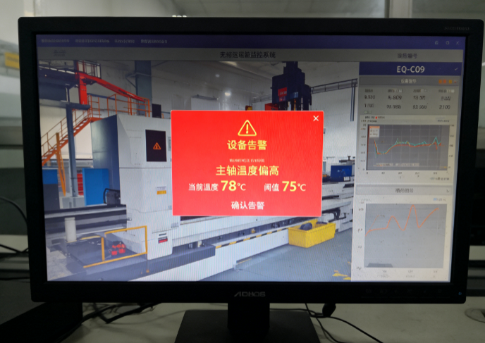
Alarm and event management: Multi-level alarm rules and linkage mechanisms such as audible-visual alerts, SMS/APP push and automatic work order generation are provided. Alarms are managed in a closed loop of confirmation, handling and closure, with the complete event handling process recorded.
Predictive maintenance: Based on historical data and machine learning models, equipment health status is assessed and failure trends are predicted, with potential failures and recommended maintenance timing prompted in advance, realizing the shift from “repair after failure” to “maintain before failure.”
Work order and O&M process management: The system supports the issuance, execution, acceptance and archiving of various O&M tasks such as patrol inspection, maintenance, repair and spot checks, standardizing work procedures and improving O&M efficiency and quality.
Energy and energy-efficiency analysis: Statistics and analysis are performed on energy consumption data such as electricity, water and gas consumption of equipment, identifying high-consumption equipment and energy-efficiency anomalies and assisting in energy-saving and consumption-reduction decisions.
Reporting and visualization: Diverse reporting tools are provided, such as daily/weekly/monthly operation reports, failure statistical analysis and O&M performance statistics, presented intuitively in charts and dashboards.
1.4 Application Value of the System
The deployment of the equipment O&M monitoring system brings practical value to enterprises in multiple aspects. In terms of safety, the system provides early warning and rapid localization of abnormal status of critical equipment, effectively preventing safety production accidents caused by equipment failures. In terms of efficiency, real-time monitoring and automatic alarms replace a large amount of manual inspection, reduce troubleshooting time and improve O&M response speed. In terms of cost, predictive maintenance reduces unscheduled downtime and spare parts waste, while energy analysis supports energy saving and consumption reduction, resulting in a significant drop in overall O&M cost. In terms of management, the data-driven O&M model makes equipment management more standardized, transparent and traceable, providing a reliable basis for management decisions. The system has become an important vehicle for realizing digitized equipment management and intelligent O&M across many industries, with broad application prospects and promotion value.
Chapter 2 Industry Application Scenarios
The equipment O&M monitoring system is applicable to a variety of industries that impose high requirements on continuous equipment operation, safety and reliability. This chapter selects seven typical industries—intelligent manufacturing, energy and power, rail transit, healthcare, data centers and information and communications, chemical and petrochemical and hazardous chemicals, and municipal utilities and smart cities—and, in view of the equipment characteristics and management pain points of each industry, describes the system's application scenarios in actual production and operation, explaining the scenario background and the system application process.
2.1 Intelligent Manufacturing
Intelligent manufacturing is one of the industries where the equipment O&M monitoring system is most widely applied and most urgently needed. In modern smart factories, a large number of production equipment items—including CNC machine tools, industrial robots, automated conveyor lines, injection molding machines, stamping equipment and welding equipment—are densely deployed and operate continuously, and their operating status directly determines capacity, quality and delivery lead time. Three typical application scenarios are described below.
2.1.1 Scenario 1: Predictive Maintenance of Production Equipment
Scenario Background: In manufacturing enterprises, production equipment is the core carrier of production capacity. The unexpected downtime of any critical machine can bring the entire production line to a halt, delay order delivery and cause economic losses. Traditional equipment maintenance mostly combines “corrective maintenance after failure” with “periodic preventive maintenance”: corrective maintenance is only carried out as an emergency repair after a failure has already occurred and production has been interrupted, being reactive and costly; periodic maintenance follows a fixed cycle and is prone to waste from premature maintenance or to missed maintenance when equipment has already deteriorated before the scheduled cycle. Equipment failures are usually gradual: from early subtle anomalies to complete failure there is often a window of several hours or even days. Yet relying on manual spot checks and experience makes it difficult to capture these early signals, causing many failures that could have been eliminated in advance to end in unscheduled downtime.
System Application Process: To address the above pain points, the system deploys multiple types of sensors for vibration, temperature, current and pressure on critical production equipment, and uploads the acquired data to the system platform in real time through industrial gateways. The platform is built in with health assessment and fault diagnosis algorithms that analyze features such as vibration spectra, temperature trends and current waveforms to automatically establish a normal operating baseline for each machine. When a certain indicator deviates from the baseline or shows characteristic degradation, the system generates a predictive maintenance alarm and provides the likely failure type, failure confidence, remaining usable time and recommended handling measures. Based on the predictive work orders generated by the system, O&M personnel prepare spare parts in advance and arrange maintenance windows, completing targeted maintenance during planned downtime gaps—thereby converting uncontrollable unscheduled downtime into controllable planned maintenance, significantly reducing equipment failure rates, extending equipment service life and cutting maintenance cost.
2.1.2 Scenario 2: Real-Time Monitoring and Alarming of Production-Line Equipment
Scenario Background: Large manufacturing enterprises usually have multiple production lines and hundreds or even thousands of equipment items distributed across several workshops and even multiple plant areas, with vastly different operating statuses. Relying on manual inspection is not only labor-intensive and inefficient but also hard to achieve round-the-clock coverage; by the time inspectors reach the site, the equipment has often already been abnormal for some time. Some workshops are dense with equipment, noisy and complex in environment, and manual inspection also entails certain safety risks. Managers need a platform that can grasp the overall equipment operating status of the entire plant in a unified and real-time manner, so as to detect anomalies at the earliest moment and respond quickly.
System Application Process: The system deploys data acquisition gateways at the workshop level, integrating the operating status, start/stop information, process parameters and output data of equipment on each production line into the platform, forming a three-level visualization view of workshop, production line and equipment. The monitoring screens and web pages refresh equipment status in real time: normal equipment displays green, while abnormal equipment automatically turns yellow or red and triggers audible-visual alarms. The system supports graded alarm rules, distinguishing general prompts from serious failures, and promptly notifies the responsible personnel via SMS and APP push. When a failure occurs, the system automatically records the failure time, failure code and associated parameters to help maintenance personnel quickly identify the cause; at the same time it automatically generates a repair work order and assigns it to the corresponding team, realizing a full closed loop of alarming, dispatching, repairing and acceptance, greatly shortening the failure response time and ensuring continuous and stable operation of the production line.
On the basis of the alarm closed loop, the system also provides managers with multi-dimensional operational analysis views. The platform automatically compiles indicators such as the overall equipment effectiveness, failure frequency and mean time to repair of each production line, forming performance comparisons among teams and equipment, helping managers identify bottleneck equipment and weak links and providing data support for production scheduling and investment decisions. Through mobile terminals, O&M personnel can receive alarms, view equipment details, upload on-site images and handling results, achieving efficient O&M anytime and anywhere and further improving the refined level of workshop equipment management.
2.1.3 Scenario 3: Full-Lifecycle and Energy Consumption Management of Equipment
Scenario Background: Equipment management covers not only operation monitoring but also the full lifecycle of equipment from selection and procurement, installation and commissioning, use and maintenance, repair and retrofit, to scrapping and disposal. Many manufacturing enterprises have unclear equipment asset inventories and incomplete registers, with scattered maintenance records, making it difficult to accurately assess the service life, repair cost and performance changes of each machine. Meanwhile, equipment energy consumption is an important component of production cost; high-consumption, low-efficiency equipment operating for long periods causes considerable waste, yet enterprises often lack refined energy consumption data and cannot locate the high-consumption links.
System Application Process: This system establishes a unified equipment asset register covering full-lifecycle information such as basic equipment information, technical archives, maintenance records, repair history, spare parts usage and responsible persons, realizing refined “one machine, one file” management. The system automatically records the execution of every maintenance, repair and inspection task, forming a complete O&M track record that helps managers assess equipment health trends and maintenance quality. In energy management, the system acquires and statistically analyzes data on equipment electricity, water and gas consumption in real time, automatically generating energy consumption reports and energy-efficiency comparisons to identify high-consumption equipment and abnormal consumption periods. Managers can accordingly optimize production scheduling, adjust operating strategies and implement energy-saving retrofits, reducing energy cost while ensuring production, and achieving synergistic optimization of equipment management and energy management.
2.2 Energy and Power
The energy and power industry is an important basic industry vital to the national economy and people's livelihoods. The various equipment in its power generation, transformation, transmission and distribution segments operates for long periods under high voltage, high temperature and continuous operation, imposing extremely high requirements on equipment safety and reliability. The equipment O&M monitoring system plays an irreplaceable role in power generation and transmission/distribution management.
2.2.1 Scenario 1: Remote Monitoring of Power Generation and Substation Equipment
Scenario Background: Power plants and substations are the core sites of power generation and transformation. They house a large number of critical equipment items such as turbo-generator sets, boilers, transformers, switchgear and relay protection devices. These equipment items operate at full or high load year-round in complex environments; once a failure occurs, it may at best reduce the unit's output and at worst cause a large-area blackout. The equipment in plants and stations is numerous and widely distributed, and some stations are located in remote areas with limited on-duty personnel; relying on manual periodic inspection makes it hard to grasp equipment operating status in real time, and in particular key parameters such as transformer oil temperature, winding temperature and switchgear contact temperature are difficult to monitor continuously by hand.
System Application Process: The system deploys sensors for temperature, vibration, oil level, pressure and partial discharge on plant and station equipment, and integrates existing monitoring data from unit DCS and substation integrated automation systems into the platform, forming a centralized monitoring view of plant and station equipment. The platform displays the operating parameters of each unit and transformer in real time; when a parameter exceeds limits or symptoms such as partial discharge or abnormal temperature appear, the system automatically raises an alarm and prompts associated protection actions. O&M personnel can view equipment status, retrieve historical curves and conduct trend analysis anytime through remote monitoring screens or mobile terminals, promptly discovering hidden hazards. The system also supports assisted remote inspection of plants and stations, helping on-duty personnel quickly locate abnormal equipment, shortening troubleshooting time and safeguarding power generation and power supply.
The system also supports the integration of video surveillance, access control and environmental information of plants and stations, realizing linked analysis of equipment status and environmental conditions. The platform automatically generates unit operation daily reports, equipment reliability statistics and maintenance recommendation reports, assisting plant and station managers in optimizing operating modes and rationally arranging maintenance plans. Through centralized and intelligent equipment management, plants and stations shift from reliance on manual experience to data-driven refined O&M, effectively improving equipment availability, reducing O&M cost and providing solid support for safe and stable operation of the power grid.
2.2.2 Scenario 2: Status Monitoring of Transmission/Distribution Lines and Distribution Areas
Scenario Background: Transmission and distribution lines stretch for hundreds of kilometers across mountainous terrain, rivers, cities and other varied topography. Towers, conductors, insulators and distribution transformers are exposed to outdoor environments for long periods and are affected by lightning, strong winds, icing, contamination and external damage, resulting in numerous hidden hazards that are not easily detected in time. Traditional inspection relies on manual patrols along the lines, which is labor-intensive and long-cycle and cannot cover all lines, so many hidden hazards are hard to detect before they develop into failures. Distribution areas have an enormous number of devices spread over many points and a wide area, and supply reliability management likewise faces major challenges.
System Application Process: By deploying online monitoring devices for micro-meteorology, inclination, vibration, icing and imaging on towers and lines, the system provides real-time perception of the line operating environment and body status, and transmits the data back to the platform via wireless networks. Combined with line registers and geographic information, the platform forms an overview of line operating status; when abnormalities such as icing exceeding limits, tower inclination, foreign object contact with conductors or partial discharge are detected, the system automatically raises alarms and localizes to the specific tower section, assisting O&M personnel in carrying out targeted maintenance. For distribution areas, the system monitors the operating load, three-phase imbalance, outage events and voltage quality of area transformers, automatically compiling outage and restoration records to help utilities quickly identify faulty areas, assess supply reliability, optimize distribution network operation management and improve customer supply satisfaction.
The system supports linkage with geographic information systems, combining line monitoring data and alarm information with map localization to present line operating status intuitively and assist O&M teams in planning patrol routes and rapidly reaching failure sites. The platform automatically aggregates records of line fault trips, lightning strikes and external damage events and conducts statistical analysis of failure causes, providing a basis for line retrofits and differentiated O&M. By combining online monitoring with data analysis, power suppliers can arrange maintenance resources more scientifically and improve line supply reliability.
2.2.3 Scenario 3: O&M Management of New Energy Station Equipment
Scenario Background: With the advancement of the “dual carbon” strategy, a large number of wind and solar power stations have been constructed and connected to the grid. Wind farms are distributed in mountainous, desert and offshore areas with harsh environments, with numerous wind turbines located in remote places; solar stations have huge numbers of modules, inverters and combiner boxes, with equipment exposed outdoors for long-term operation. New energy stations generally face prominent problems such as dispersed equipment, difficult inspection, high O&M cost and difficult fault localization; once equipment fails, it directly affects power generation and causes economic losses.
System Application Process: Oriented to wind farms and solar stations, the system integrates operating data from the various wind turbine subsystems, PV inverters, combiner boxes and box-type transformers into the platform. The platform monitors parameters such as turbine speed, generator temperature, vibration and generation power in real time, automatically identifying and alarming on abnormal units; it conducts intelligent analysis of PV module generation efficiency, inverter conversion efficiency and abnormally heated modules to quickly locate low-efficiency equipment and faulty branches. Combined with weather forecasts and generation predictions, the system optimizes station O&M plans and reduces unnecessary inspections. Through the platform, O&M personnel can remotely view station operating status and centrally handle alarms and work orders, greatly improving the O&M efficiency of new energy stations, reducing cost and ensuring power generation.
The system also interfaces with station centralized monitoring and energy management systems, uniformly displaying core indicators such as total station generation, available hours and equipment availability. The platform automatically generates equipment failure statistics and generation-loss analysis reports, helping O&M teams assess the impact of failures on generation and optimize spare parts and maintenance resource scheduling. Through centralized, intelligent station O&M management, new energy enterprises can significantly reduce on-site staffing, lower O&M cost, improve failure-handling timeliness and ensure safe and efficient station power generation.
2.3 Rail Transit
Urban rail transit and railway transportation feature large capacity, high speed, high safety requirements and long operating hours. Their trains, signaling, power supply, environmental control and platform screen doors constitute a highly complex electromechanical system. Once rail transit equipment fails, it directly affects traffic safety and operating order, imposing extremely high requirements on equipment status monitoring.
2.3.1 Scenario 1: Status Monitoring of Metro Trains and Signaling Equipment
Scenario Background: Metro trains operate at high frequency and density every day. Vehicles involve numerous subsystems such as traction, braking, doors, air conditioning and signaling; equipment wears quickly and failures have a large impact. The signaling system is the “brain” of metro operation, controlling safe train intervals and routes; a signaling equipment failure can cause train delays or even shutdowns. Metro operation features short nighttime maintenance windows and the inability to shut down for maintenance during the day, so equipment failures often have to be quickly located and handled in operating gaps. Meanwhile, because trains run in sections, the transmission and real-time monitoring of status information between train and ground is a key difficulty in realizing intelligent O&M.
System Application Process: Relying on on-board monitoring devices and communication networks, the system acquires in real time the operating status and fault codes of each critical train system and uploads them to the ground O&M platform through train-ground wireless communication, realizing remote real-time monitoring of train operating status. The platform conducts health trend analysis of key vehicle components such as traction, braking and doors; when anomalies or pre-alarms are detected, it automatically generates maintenance prompts to help maintenance personnel carry out targeted checks during the nighttime maintenance window, reducing blind troubleshooting. For signaling equipment, the system integrates the status information of signals, switches, track circuits and on-board ATP/ATO devices, displaying equipment online status and action records in real time and promptly alarming on abnormal switch conversion and signal failures. Through centralized monitoring, operating companies can fully grasp the operating status of trains and signaling equipment, detect hidden hazards in advance and ensure traffic safety and punctual operation.
The system supports historical replay and comparative analysis of train operating data, helping maintenance personnel review failure processes and trace abnormal causes. The platform can also interface with operation dispatching and maintenance management systems to achieve coordinated linkage of failure information, maintenance plans and operating arrangements, reducing the impact on normal operation. Through centralized, data-based monitoring of trains and signaling equipment, metro operators can comprehensively improve the foresight and precision of equipment O&M, ensuring safe and punctual metro operation.
2.3.2 Scenario 2: Operation Monitoring of Station Electromechanical Equipment
Scenario Background: Metro stations house a large number of electromechanical equipment items such as elevators and escalators, platform screen doors, ventilation and air conditioning, water supply and drainage, low-voltage power distribution and fire protection, which safeguard the safe operation of the station and the comfort of passengers. Station equipment is numerous, varied in type and widely distributed, and all types of inspection and maintenance must be completed after the end of nighttime operation and before the start of early-morning operation, leaving tight and heavy maintenance workloads. Once equipment fails, it may affect passenger travel safety and normal station operation—for example, a screen door failure may prevent a train from departing, and an escalator failure may cause passenger entrapment or injury.
System Application Process: The system connects the various electromechanical equipment in stations to a unified integrated monitoring platform, acquiring equipment operating status, energy consumption and environmental parameters in real time. Through station floor plans and equipment lists, the platform intuitively displays the online status of each device, automatically alarming on abnormal devices and localizing them to specific positions. The system conducts statistical analysis of screen door opening/closing counts, escalator running time and air conditioning unit operating status, establishing equipment degradation trend models to pre-warn potential failures. For the nighttime maintenance scenario, the system supports batch issuance of inspection tasks, recording of inspection results and generation of inspection reports, standardizing nighttime maintenance procedures. Through centralized monitoring and intelligent O&M, station equipment management shifts from “dispersed manual inspection” to “centralized automatic monitoring,” effectively improving station equipment O&M efficiency and operational safety.
The system supports classified statistics of station energy consumption, identifying high-power, high-consumption equipment and assisting stations in formulating energy-saving operation strategies. The platform records every failure handling and repair process, forming station equipment O&M archives that provide a basis for equipment evaluation and renewal. Through unified dispatching on the integrated monitoring platform, station on-duty personnel can grasp the status of all electromechanical equipment on a single interface, greatly improving inspection efficiency and failure response speed, ensuring safe and orderly station operation and enhancing the passenger travel experience.
2.3.3 Scenario 3: Overhaul and O&M of High-Speed EMUs
Scenario Background: High-speed EMUs run at high speed with high running density and extremely high safety standards, and generate a large amount of operating data during operation. The overhaul of EMUs adopts a planned preventive maintenance regime that requires rational maintenance arrangements based on running mileage, running time and equipment status. Because EMUs are numerous, overhaul bases are relatively centralized and overhaul work time is tight, how to efficiently use maintenance windows, precisely grasp the status of each component of each train, and avoid both over-maintenance and missed maintenance is an important issue faced by EMU running depots.
System Application Process: The system gathers on-board monitoring data, operational fault records and overhaul histories of EMUs into the overhaul base O&M platform. The platform conducts health assessment of each train subsystem and automatically compiles statistics on the running mileage, failure frequency and repair records of each component, providing data support for planned maintenance and condition-based maintenance. When a train returns to the depot for overhaul, the system automatically aggregates the alarms and abnormal information during the current operation, prompting maintenance personnel to focus on key inspection points and reducing blind checks. The system also supports life prediction of wearing parts and critical components, proactively prompting replacement timing and rationally arranging spare parts inventory. Through data-driven EMU O&M, overhaul units can schedule maintenance plans more precisely, optimize maintenance processes and improve maintenance quality and efficiency, ensuring safe and stable operation of EMUs.
The system also supports process management and quality traceability of overhaul work: electronic work orders standardize maintenance procedures, and overhaul progress and results are recorded in real time, making the entire overhaul process queryable and traceable. The platform combines overhaul data with vehicle health models to continuously optimize maintenance cycles and items, driving EMUs from planned maintenance toward condition-based and predictive maintenance. Through digital overhaul management, overhaul units can improve the utilization efficiency of maintenance resources, enhance EMU availability and ensure safe and efficient high-speed railway operation.
2.4 Healthcare
Hospitals are important places that safeguard people's life and health. The normal operation of medical equipment is directly related to diagnostic accuracy and patient treatment outcomes. Large medical equipment is expensive, structurally complex and highly demanding on the operating environment, so equipment O&M monitoring has important practical significance in the healthcare industry.
2.4.1 Scenario 1: Operation Monitoring of Large Medical Imaging Equipment
Scenario Background: CT, MRI, DR, ultrasound and other large medical imaging equipment are the core equipment for clinical diagnosis in hospitals. Each unit is high in value, high in frequency of use and complex in technology. These devices impose strict requirements on power supply quality, ambient temperature and humidity and cooling systems; once the operating environment is abnormal or equipment components degrade, the result may at best affect image quality and at worst cause equipment shutdown, directly affecting patient examination scheduling and clinical diagnosis progress. During equipment failure downtime, patient examinations accumulate, departmental schedules are disrupted and repair costs may rise. Imaging department equipment is usually centrally managed, but the equipment is numerous and operating parameters are complex, making it difficult for staff to continuously track the operating details of every device.
System Application Process: The system deploys monitoring and acquisition devices on large imaging equipment such as CT and MRI, acquiring in real time key information such as supply voltage, current, coil temperature, cooling water temperature, X-ray tube exposure count and equipment operation logs, and uploading it to the hospital equipment management platform via networks. The platform monitors the operating status of each device in real time; when supply anomalies, excessive temperature, cooling system failure or component performance degradation are detected, it automatically triggers alarms and pushes them to equipment engineers and department heads. The system compiles statistics on the cumulative exposure of wearing components such as X-ray tubes and, combined with manufacturer maintenance requirements, predicts replacement timing and arranges maintenance in advance. The system also integrates equipment repair records, warranty information and manufacturer service responses to form complete equipment archives, helping hospitals scientifically manage imaging equipment assets, reduce equipment failure downtime and ensure the continuity of examination services.
The system supports associating equipment operating data with repair work orders and manufacturer maintenance information; when an anomaly occurs, it automatically indicates warranty status and recommended handling procedures, assisting equipment engineers in efficiently coordinating handling. The platform can also conduct statistical analysis of the utilization rate, examination volume and failure downtime of all large equipment in the hospital, providing data references for hospital equipment procurement, renewal and departmental operation decisions. Through professional medical equipment monitoring, hospitals can significantly reduce equipment failure downtime, ensure timely imaging examinations and improve the patient experience and the quality of medical services.
2.4.2 Scenario 2: Monitoring of Hospital Purification and Logistics Support Systems
Scenario Background: Areas such as operating rooms, ICUs, clean wards and clinical laboratories impose strict requirements on environmental cleanliness, temperature and humidity, and differential pressure. Once anomalies occur in logistics support equipment such as operating room air purification systems, constant temperature and humidity systems, medical gas systems and central air conditioning, they may directly affect surgical safety and patient health. Hospital logistics equipment is distributed across various buildings and floors, is diverse in type and demands rapid failure response. Meanwhile, hospitals must guarantee uninterrupted power supply, so the status management of backup power supplies and UPS equipment is equally important.
System Application Process: The system connects purification units, supply and exhaust air systems, differential pressure monitoring and temperature/humidity sensors in operating rooms and clean areas to the platform, monitoring in real time the air purification effect and environmental parameters of each clean area; when differential pressure is abnormal, temperature/humidity exceeds limits or purification units fail, the system immediately raises alarms and prompts handling. The system centrally monitors the hospital-wide logistics support systems of central air conditioning, water supply and drainage, medical gas and power supply, grasping the operating status and energy consumption of each system in real time. For backup power supplies and UPS, the system monitors battery status, charge/discharge conditions and switching reliability, and prompts inspection and maintenance on a regular basis. Through centralized monitoring and alarm linkage of logistics support equipment, hospitals can promptly detect and quickly handle equipment anomalies, ensuring stable clean environments and safe, reliable operation of logistics systems, thereby providing solid logistics support for medical services.
2.5 Data Centers and Information and Communications
Data centers are the infrastructure of the digital economy and information and communications. The stable operation of the computer room power, cooling, network and security systems directly determines business continuity. With the rapid development of cloud computing, big data and artificial intelligence, data center scales continue to expand, imposing higher requirements on the O&M management of computer room infrastructure.
2.5.1 Scenario 1: Computer Room Power and Environment Monitoring
Scenario Background: The power and environment equipment in data center computer rooms—UPS uninterruptible power supplies, power distribution cabinets, diesel generators, precision air conditioners, fresh air systems and water leak detection—forms the basis for ensuring continuous and stable operation of servers and network equipment. Computer rooms impose extremely high requirements on temperature, humidity and power supply continuity; once a UPS fails, utility power is interrupted, precision air conditioners shut down or a water leak occurs, servers may rapidly overheat and crash, causing business interruption and enormous economic losses. Computer room equipment is numerous and the systems are complex, and 7×24 hour uninterrupted monitoring is required, which manual duty and inspection cannot fully cover, especially at night and during holidays—the weak links of O&M.
System Application Process: The system deploys temperature/humidity sensors, water leak detection, smoke detectors, access control and power monitoring instruments in the computer room, integrating the status of power equipment such as UPS, precision air conditioners, distribution cabinets and generators into the power and environment monitoring platform. The platform monitors in real time the computer room temperature/humidity distribution, UPS load and battery status, air conditioner operating status, and the switching between utility power and diesel generators, forming a panoramic view of the computer room environment and power system. When temperature/humidity exceeds limits, a UPS fails, a water leak alarm occurs or power supply is abnormal, the system immediately raises alarms via audible-visual signals, SMS and APP, and links to access control and fire protection systems. The platform automatically records alarms and handling processes and generates operation reports, helping O&M personnel promptly discover hidden hazards and quickly handle them, ensuring safe and stable computer room operation.
The system supports refined statistics of computer room energy consumption and tracking analysis of energy-efficiency indicators such as PUE, assisting computer rooms in optimizing cooling and power supply strategies and advancing energy saving and consumption reduction. The platform also supports centralized unified management of multiple computer rooms and sites; managers can grasp the operating status of each computer room on a single dashboard, achieving unified dispatching and remote management. Through the integration of power/environment monitoring and O&M management, data center O&M personnel can discover hidden hazards before failures occur and handle them quickly after failures, significantly improving the reliability of computer room infrastructure and O&M efficiency.
2.5.2 Scenario 2: Health Monitoring of Servers and Network Equipment
Scenario Background: The IT equipment in data centers—servers, storage, switches and routers—is numerous and carries various business systems. IT equipment failures, performance bottlenecks or exhausted resources all lead to business lag, crashes or even data loss. As data centers expand, how to quickly discover failures among massive equipment, assess equipment health and optimize resource utilization has become a core challenge of O&M management. Traditional passive reactive O&M tends to troubleshoot only after the business has already been affected, making it difficult to meet high-availability requirements.
System Application Process: Through networks and agents, the system collects indicators such as server CPU utilization, memory usage, disk space, network traffic and process status, performing real-time health monitoring of equipment. The platform establishes equipment performance baselines; when an indicator is persistently abnormal or approaches its upper limit, it automatically raises alarms and prompts scaling or optimization suggestions. The system monitors network equipment port status, link traffic, packet loss rate and device load, promptly discovering link congestion and device failures and assisting network O&M in quickly locating problems. The system also supports asset management, automatically inventorying IT equipment lists and recording configuration information and change history to form data center IT asset registers. Through proactive health monitoring and intelligent alarming, O&M teams can intervene before failures affect the business, improving the overall availability of the data center.
The system supports alarm aggregation and intelligent noise reduction, converting massive monitoring data into clear alarm events, helping O&M personnel focus on key issues and reducing alarm fatigue. The platform can also conduct correlation analysis of resource consumption of business systems, assisting capacity planning and performance tuning to ensure stable operation during business peaks. Through proactive, intelligent IT infrastructure monitoring, data centers can shift from passive to proactive and intelligent O&M, comprehensively improving the availability and service levels of business systems.
2.6 Chemical, Petrochemical and Hazardous Chemicals
The chemical and petrochemical industry features complex production environments involving hazards such as high temperature, high pressure, flammability, explosiveness and toxicity. Safe equipment operation is the bottom line of safe production. Any anomaly in production units and storage and transportation facilities may cause serious safety accidents, so the requirements on equipment status monitoring and safety warning are extremely strict.
2.6.1 Scenario 1: Safety Monitoring of High-Risk Process Units
Scenario Background: Chemical production units operate for long periods under high temperature and high pressure, involving complex processes such as reaction, distillation, heat exchange and compression. Reactors, compressors, heat exchangers and heating furnaces are critical to safe production. Once a unit experiences overtemperature, overpressure, leakage or equipment anomaly, it may trigger major accidents such as fire, explosion or poisoning. Chemical enterprises generally implement strict safe production management systems and need to monitor the operating status of critical process parameters and critical equipment in real time, continuously and reliably. However, some units have aging equipment and harsh on-site environments, and hazardous areas cannot be frequently inspected manually, making it difficult to fully grasp equipment safety status through traditional means.
System Application Process: The system deploys monitoring instruments for temperature, pressure, liquid level, flow, combustible gas and toxic gas at critical equipment and process nodes of chemical units, integrating data from safety interlock systems such as DCS and SIS into the safety monitoring platform. The platform monitors critical process parameters in real time with trend analysis, sets multi-level alarm thresholds and interlock prompts; when a parameter abnormally approaches a dangerous value, the system automatically pre-warns and links on-site audible-visual alarms. The system monitors the vibration and temperature of critical rotating equipment such as compressors and pumps, identifying early failures such as bearing wear and misalignment through spectrum analysis. The platform also combines inspection robots and online monitoring to conduct remote inspection of equipment in hazardous areas, reducing personnel exposure risk. Through centralized safety monitoring of high-risk units, enterprises can promptly discover and eliminate hidden hazards, ensuring production safety.
The system supports statistical analysis of historical operating data and alarm records of units, identifying high-frequency alarm points and weak equipment links to provide a basis for process optimization and equipment retrofit. The platform can also interface with enterprise safety management systems and emergency command systems to quickly retrieve equipment status and alarm information in emergencies, assisting emergency decision-making. Through the integration of process parameters, equipment status and safety monitoring, chemical enterprises can build a safety prevention and control system covering the entire production process, effectively improving the level of intrinsic safety.
2.6.2 Scenario 2: Monitoring of Pumps, Valves, Storage Tanks and Pipeline Facilities
Scenario Background: Chemical and oil product storage and transportation facilities include various storage tanks, transfer pumps, valves and long-distance pipelines. These facilities store and transport large quantities of flammable and explosive media and are high-risk links for safety accidents. Tank liquid level overrun, overpressure and corrosion leakage, pump and valve seal failure and leakages, and pipeline corrosion thinning and rupture leakage can all lead to major accidents and environmental pollution. Tank farms and pipeline areas are wide in distribution and many in points with long lines; manual inspection cannot achieve real-time full coverage, and hidden hazards such as combustible gas accumulation in tank farms and tiny pipeline leakages are difficult to detect by hand.
System Application Process: The system deploys monitoring devices for liquid level, pressure, temperature, combustible gas and tank-bottom leakage on storage tanks, providing all-around monitoring of the tank farm and grasping storage tank operating status in real time. When liquid level overruns, pressure is abnormal or combustible gas leakage is detected, the system automatically raises alarms and links emergency shutoff and sprinkler systems to prevent the situation from escalating. For pumps and valves, the system monitors their operating status, seal performance and leakage, automatically generating inspection and maintenance prompts to promptly discover leakages. For long-distance pipelines, the system deploys pressure, flow, leak detection and cathodic protection monitoring devices, promptly detecting pipeline leakage through pressure wave and flow balance analysis and localizing the approximate leak section to assist emergency repair. Through comprehensive monitoring of storage and transportation facilities, enterprises can effectively prevent leakage accidents and ensure the safety of the storage and transportation link.
2.7 Municipal Utilities and Smart Cities
With the in-depth advancement of smart city construction, urban municipal public facilities such as water supply, power supply, gas, elevators, streetlights and drainage are gradually realizing digital management. Municipal public facilities are many in points and wide in coverage and are closely related to citizens' daily lives; the equipment O&M monitoring system provides strong support for the safe and efficient operation of urban infrastructure.
2.7.1 Scenario 1: Safety Monitoring of Elevators and Special Equipment
Scenario Background: Elevators are indispensable vertical transportation tools in modern high-rise buildings and are closely related to residents' daily lives and life safety. Elevators are numerous, varied in brand and model, and extremely high in use frequency; long-term operation is prone to hidden hazards such as traction machine wear, wire rope aging, door lock failure and control system anomalies. Elevator failures may cause safety accidents such as passenger entrapment and falling elevators, attracting social attention. Traditional elevator maintenance mainly relies on periodic manual maintenance and post-failure repair; the actual operating status and maintenance quality of elevators are difficult to supervise effectively, and sudden failures such as passenger entrapment are hard to respond to and handle quickly.
System Application Process: The system deploys monitoring devices in elevator cars, machine rooms and control cabinets, acquiring in real time data such as elevator operating status, floor position, door opening/closing status, running speed and fault codes, and uploading them to the elevator O&M monitoring platform via the Internet of Things. The platform monitors each elevator in real time; when an elevator experiences passenger entrapment, failure shutdown or operating anomaly, the system automatically raises an alarm and pushes information to property management, maintenance units and the regulatory platform, supporting one-click rescue linkage to shorten entrapment rescue time. The system automatically compiles elevator operation counts, door opening/closing counts, fault records and maintenance cycles, assesses elevator health status, prompts maintenance priorities and assists in supervising elevator maintenance quality. Through elevator IoT monitoring, urban elevator safety management shifts from “passive repair” to “proactive monitoring and rapid rescue,” safeguarding citizens' elevator safety.
The system supports connecting elevator operating data to urban elevator emergency rescue platforms, enabling rapid localization of entrapment events and efficient dispatch of rescue forces. The platform can also evaluate the maintenance quality of elevator maintenance units, forming maintenance quality profiles based on indicators such as operational failure rate and entrapment count to assist regulatory authorities in precise supervision. Through the promotion and application of elevator IoT monitoring, the level of urban elevator safety management continuously improves, effectively safeguarding the life and property safety of the people.
2.7.2 Scenario 2: Operation Monitoring of Municipal Water Utilities and Public Facilities
Scenario Background: Urban public facilities such as water supply, drainage, pump stations, sewage treatment and streetlighting are the “lifelines” of urban operation. Insufficient water supply network pressure, pipe bursts and leaks, pump station pump failures, drainage facility blockages and large-scale streetlight failures all affect normal urban operation and residents' quality of life. Municipal facilities are widely distributed, scattered in points and diverse in operating environments; traditional manual inspection is inefficient and costly and cannot grasp the operating status of various facilities in real time, with limited emergency response capability.
System Application Process: The system deploys pressure, flow and water quality monitoring equipment at key nodes of the water supply network and pump operating status, liquid level and power monitoring devices at pump stations, grasping the operating status of the water supply system in real time. When network pressure is abnormal, a pipe burst occurs or pump station equipment fails, the system automatically raises alarms and assists in localizing the failure area, supporting remote dispatching and rapid repair. For drainage facilities, the system monitors pump station liquid level, pump operation and pipe network water level, promptly warning of waterlogging risks. The system also centrally monitors the switching status, power consumption and failures of urban streetlights, promptly discovering line faults and lights-out conditions and rapidly arranging repairs. Through centralized monitoring and intelligent dispatching of municipal public facilities, urban managers can grasp infrastructure operating status in real time, respond quickly to various emergencies and improve urban operation support capability and public service levels.
The system supports integrating operating data of various municipal facilities such as water supply, drainage and streetlighting into a unified urban operation monitoring platform, achieving cross-department, cross-system data sharing and coordinated linkage. Combined with geographic information systems, the platform intuitively displays the distribution and status of various facilities, supports statistical analysis and trend prediction of historical data, and assists managers in optimizing facility maintenance plans and rationally allocating resources. Through intelligent management of municipal public facilities, urban managers can promptly discover and handle various hidden faults, improve the operating efficiency and emergency response capability of urban infrastructure, and create a safer, more convenient and more livable urban environment for citizens.
Spécifications
Caractéristiques
- 1. Wide industry adaptability: Applicable to multiple industries and scenarios including intelligent manufacturing, energy and power, rail transit, chemical and petrochemical industries, and data centers. It boasts broad application prospects and meets the equipment operation and maintenance requirements of diverse fields.
- 2. Integrated full-process services: Leveraging technical expertise, after-sales support and industry experience, we deliver one-stop complete solutions covering system planning, scheme design, project implementation and operation & maintenance guarantee.
- 3. Excellent platform capabilities: Featuring a highly available and easily scalable system architecture that supports customized development, the platform can access heterogeneous equipment from multiple regions, manufacturers and of various types.
- 4. Outstanding data-driven value: It centrally aggregates equipment operation data to build a panoramic view of enterprise equipment assets, supporting predictive maintenance, spare parts management and energy consumption management to achieve safety improvement, efficiency enhancement and cost reduction.