Product Demo Video
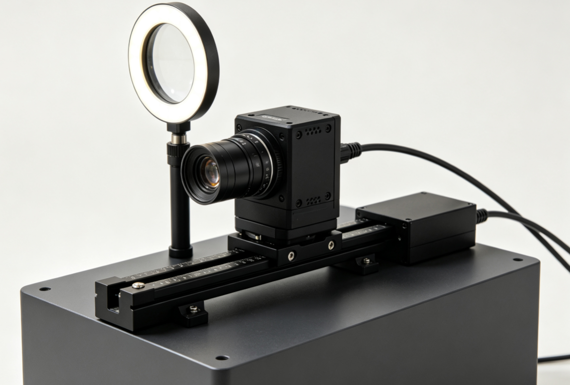
DIC video extensometer equipment
1 Preface
This series of DIC video extensometers is based on the Digital Image Correlation (DIC) method as its core technical principle. They are non-contact, high-precision, full-field three-dimensional (3D) deformation and strain measurement instruments that fundamentally overcome the inherent drawbacks of traditional mechanical extensometers, which must remain in direct contact with the test specimen. As a result, they enable zero-damage measurement, impose no limitation on the measurement range, and can be flexibly adapted to a wide variety of complex test conditions. The product line comprises three main models—HS-S3DDIC350, HS-M3DDIC360 and HS-H3DDIC380—which respectively target the three application directions of dynamic impact testing, micro-scale measurement and high-temperature extreme-environment testing. The series has been widely deployed in such industries as new-material R&D, the automotive industry, semiconductor packaging and metallurgical high-temperature testing. This specification systematically describes the equipment technical parameters, industry application solutions, customization and OEM services, installation and commissioning procedures, troubleshooting guidelines and maintenance operation standards, providing comprehensive standardized guidance for equipment operation, routine maintenance and customized cooperation.
2 Product Classification and Core Parameters
This series of DIC video extensometers includes three models—HS-S3DDIC350, HS-M3DDIC360 and HS-H3DDIC380. Each model is differentiated in terms of hardware configuration, measurement accuracy and applicable test conditions. The core technical parameters are detailed below.
2.1 HS-S3DDIC350 Video Extensometer
Core hardware configuration: two or more high-speed global-shutter industrial cameras + a high-precision high-speed synchronization control module + professional DIC dynamic analysis software + high-speed fill lighting sources. The model is specifically designed for dynamic mechanical testing scenarios such as high-speed impact, transient deformation and vibration fatigue. It can accurately capture transient deformation data on the microsecond timescale, effectively resolving long-standing industry problems in which conventional test equipment is unable to record transient strain information, suffers from data acquisition lag, or misses localized deformation.
Core Technical Parameters
Table 1 Core Technical Parameters of the HS-S3DDIC350
Parameter | Technical Specification |
Camera configuration | ≥2 high-speed global-shutter industrial cameras, free of rolling-shutter distortion |
Maximum acquisition frame rate | 25,000 fps at full resolution; up to 100,000 fps in local ROI regions |
Effective resolution | 1280 × 1024 (at full frame rate); custom resolutions supported for high-speed acquisition |
Synchronization accuracy | Timing synchronization error of the high-speed synchronization module ≤ 1 μs; no frame offset between multiple cameras |
Displacement measurement accuracy | ≤ 0.01 pixel, with synchronized 3D displacement measurement |
Strain measurement range | 0.005% to 2000%, suitable for ultra-large-deformation transient scenarios |
Strain measurement accuracy | ≤ 50 με, no data drift during dynamic measurement |
Measurement modes | 3D full-field dynamic continuous acquisition; transient single-trigger acquisition |
Applicable test conditions | Impact, explosion, high-speed tensile, high-frequency vibration and fatigue transient tests |
Data output formats | Compatible with Abaqus, ANSYS and other simulation software; supports data comparison analysis |
2.2 HS-M3DDIC360 Video Extensometer
Core hardware configuration: binocular high-resolution scientific-grade industrial cameras + high-precision microscope/telecentric lenses + a precision motorized microscope stage + a dedicated microscope fill lighting system + micro-deformation analysis software. Targeting the deformation measurement needs of small specimens and precision devices at the mesoscale and microscale, it achieves full-field strain measurement with micron- to sub-micron-level accuracy, effectively resolving industry pain points such as the difficulty of observing micro-specimen deformation, the incompleteness of single-point measurement data, and the inability to accurately quantify tiny deformations.
Core Technical Parameters
Table 2 Core Technical Parameters of the HS-M3DDIC360
Parameter | Technical Specification |
Camera configuration | Binocular high-resolution scientific-grade cameras, 12-megapixel pixel resolution |
Lens configuration | High-precision microscope/telecentric lenses, magnification adjustable from 50× to 200× |
Stage parameters | Motorized precision microscope stage, travel 50 mm × 50 mm, positioning accuracy ± 0.5 μm |
Minimum measurement field of view | 0.5 mm × 0.5 mm, suitable for micro specimens, chips and thin-film devices |
Warpage measurement accuracy | 0.1 μm, meeting flatness inspection requirements for precision semiconductor devices |
Displacement measurement accuracy | ≤ 0.005 pixel, sub-micron-level deformation resolution capability |
Strain measurement range | 0.005% to 1000%, suitable for micro-scale small deformation and large thin-film deformation |
Temperature adaptation range | -190 °C to 600 °C, supporting high-/low-temperature micro coupled tests |
Calibration accuracy | Equipped with an ultra-high-precision microscope calibration target; calibration error ≤ 0.3 μm |
Core functions | Micro full-field strain, thermal expansion coefficient (CTE), micro-warpage and interface debonding deformation measurement |
2.3 HS-H3DDIC380 Video Extensometer
Core hardware configuration: a binocular 3D stereo high-definition measurement mainframe + a high-temperature-resistant optical observation window + a dedicated cold-light illumination system + a spectral filtering component + high-temperature deformation analysis software. It effectively overcomes such technical difficulties as thermal radiation interference, light distortion, image overexposure and data inaccuracy in high-temperature environments, enabling full-field 3D deformation and strain measurement of materials and components under ultra-high-temperature conditions. It is suited to application scenarios including the metallurgical industry, aerospace high-temperature materials and high-temperature component reliability testing.
Core Technical Parameters
Table 3 Core Technical Parameters of the HS-H3DDIC380
Parameter | Technical Specification |
Mainframe configuration | Binocular 3D stereo measurement mainframe, resistant to high-temperature electromagnetic interference |
High-temperature window | Custom high-purity quartz optical window, temperature resistance ≥ 2300 °C, transmittance ≥ 92% |
Illumination system | High-power dedicated cold-light source, no thermal radiation, suitable for sealed high-temperature furnaces |
Filtering system | Customized spectral filtering component that fully removes high-temperature infrared thermal radiation interference |
Maximum measurement temperature | 1800 °C standard; 2300 °C high-temperature customization supported |
Displacement measurement accuracy | ≤ 0.02 pixel, no data drift in high-temperature environments |
Strain measurement accuracy | ≤ 80 με, common to high-temperature dynamic and static tests |
Measurement functions | Full-field strain measurement for high-temperature creep, thermal expansion, thermal warpage and high-temperature tensile/compression |
Compatible equipment | High-temperature muffle furnaces, vacuum high-temperature test furnaces and high-temperature tensile testing machines |
Interference immunity | Isolates thermal airflow disturbance and high-temperature strong-light interference; stable, distortion-free image acquisition |
3 Applications and Detailed Scenarios by Model
3.1 HS-S3DDIC350 Application Industries and Scenarios
The HS-S3DDIC350 focuses on high-speed dynamic, transient impact and high-frequency fatigue measurement, with core applications covering the automotive industry and the mechanical R&D of new materials. It can accurately capture the complete transient process of deformation, fracture and rebound on the millisecond-to-microsecond timescale, effectively compensating for the shortcoming that conventional static measurement equipment cannot accommodate extreme dynamic test conditions.
3.1.1 High-Speed Impact Damage Testing of Aerospace Composite Materials
Scenario background: The wings and fuselage structures of aircraft rely heavily on carbon-fiber composites and honeycomb sandwich composites. When subjected to high-speed loads such as bird strikes, airborne gravel impacts and takeoff/landing vibration impacts, such materials are highly prone to transient damage including delamination, cracking and local collapse; moreover, the damage process is extremely brief and the deformation is irreversible. Conventional mechanical extensometers cannot keep up with the speed of high-speed impacts for data acquisition, while single-point sensors can only obtain localized information and cannot reconstruct the overall damage evolution, leaving the assessment of material impact resistance incomplete and creating potential hidden risks in aircraft structural safety design. Consequently, the industry urgently needs a measuring device capable of full-field, high-speed, synchronized capture of transient impact deformation, so as to accurately analyze the impact failure mechanism of composite materials and thereby optimize structural design and material selection.
Equipment application process: Before testing, a uniform, high-precision artificial speckle pattern is prepared on the surface of the carbon-fiber composite specimen. Two high-speed global-shutter cameras are arranged symmetrically on both sides of the impact test platform. The high-speed synchronization module performs timing calibration of the two cameras to ensure fully synchronized frame acquisition, with the synchronization error controlled within 1 μs. Acquisition parameters are configured, and a 25,000 fps full-resolution acquisition mode is set according to the impact velocity. Trigger interlock is enabled to coordinate with the drop-weight impact testing machine and the Hopkinson pressure bar test system. Once the test begins, the impact device instantaneously applies a high-speed load, and the HS-S3DDIC350 system synchronously initiates full-field image acquisition, recording the complete 3D deformation data of the specimen from contact impact, local compression deformation, stress concentration, delamination cracking through to total failure. After the test, the dedicated DIC analysis software extracts full-field strain maps, displacement distributions and damage propagation paths at different instants, precisely locating stress-concentration regions and quantifying maximum strain, deformation rate and critical failure load. Meanwhile, the measured data are compared with aerospace structural simulation model data to correct simulation parameters and optimize composite laminate architecture and impact-resistant design, providing accurate data support for the reliability verification of aerospace components.
3.1.2 Transient Deformation Testing of Automotive Body Structures in Crash
Scenario background: Passive safety performance is a core indicator in whole-vehicle R&D. Body sheet metal, crash beams and door structures undergo millisecond-scale high-speed deformation, buckling and energy-absorbing deformation during frontal and side impacts, and the deformation pattern and energy-absorption efficiency directly determine occupant safety rating. Conventional testing relies on acceleration sensors and strain gauges for single-point data acquisition, which is not only complex to wire and vulnerable to damage from crash impact but also unable to obtain the full-field deformation distribution of the body, making it difficult to accurately identify structurally weak regions. As a result, the simultaneous pursuit of body lightweighting and safety optimization is difficult, and the stringent requirements of the C-NCAP new-car assessment program cannot be satisfied.
Equipment application process: In whole-vehicle or body-component crash tests, multiple high-speed global-shutter cameras are used to build the HS-S3DDIC350 measurement system, and the high-speed synchronization module unifies the timing of all devices to eliminate acquisition time differences. High-contrast speckle coatings are sprayed on key test regions of the body (crash beam, A-pillar, door sheet metal and chassis connection components). Camera focal length and illumination brightness are adjusted to ensure blur-free, smear-free images under high-speed motion. Ultra-high frame rate acquisition parameters are set, and high-speed trigger acquisition is enabled for the transient crash process, recording the full 3D displacement, full-field strain and deformation time-series data of the body during the 0–100 ms crash cycle. After testing, the software automatically generates dynamic deformation maps, strain-variation curves and energy-absorption deformation parameters, accurately analyzing the deformation time sequence, stress-concentration locations and degree of plastic deformation of the body structure. By comparing the energy-absorption effects of bodies made of different materials and structures using measured data, the body sheet-metal thickness and crash-beam structural geometry are optimized, achieving lightweighting while enhancing crash safety performance and helping automakers pass authoritative safety certification.
3.1.3 High-Speed Tensile Mechanical Property Testing of Novel Polymer Materials
Scenario background: Novel elastic polymers, flexible composite materials and ballistic polymer materials are widely used in protective equipment and flexible devices. Such materials feature ultra-large deformation and high-speed rebound characteristics, and their mechanical response under high-speed tensile loading differs greatly from that under static loading. Conventional static extensometers have low frame rates and slow response, and cannot capture key parameters during high-speed tensile such as instantaneous elastic deformation, yield transition and fracture elongation, resulting in a lack of dynamic mechanical property data that prevents accurate guidance for formulation improvement and process optimization, thereby constraining the industrialization of high-end flexible new materials.
Equipment application process: Given the small size, high deformation speed and large deformation magnitude of polymer flexible specimens, the ROI local acquisition mode of the HS-S3DDIC350 is configured to raise the acquisition frame rate to 80,000 fps while balancing acquisition precision and speed. Ultra-fine uniform speckle patterns are produced on the surface of flexible material specimens, which are then fixed in the fixture of a high-speed tensile testing machine. The 3D measurement accuracy of the two cameras is calibrated to ensure error-free 3D deformation measurement. The tensile test is started, the equipment synchronously triggers high-speed image acquisition, and the complete process of elastic deformation, plastic yield, ultimate elongation and instantaneous fracture of the specimen during high-speed tensile is continuously recorded, together with real-time full-field strain, displacement and deformation-rate data. Through software analysis, core parameters such as dynamic elastic modulus, dynamic yield strength and high-speed elongation at break are obtained, and the differences in dynamic mechanical properties of materials produced with different formulations and forming processes are compared, precisely identifying performance shortcomings and providing quantitative data support for polymer material formulation optimization and forming-process upgrades, thereby accelerating the R&D iteration of new protective and flexible materials.
3.2 HS-M3DDIC360 Application Industries and Scenarios
The HS-M3DDIC360 focuses on the measurement of micro-scale, micron-level high-precision deformation of small components, with core applications covering three directions: semiconductor microelectronics, precision material research and micro-electromechanical systems (MEMS). It enables full-field strain, micro-warpage and interface deformation detection of mesoscale and microscale specimens, resolving such industry problems as the inability to quantify small-component deformation and the difficulty of analyzing micro-failure mechanisms.
3.2.1 Thermal Warpage and Micro-Strain Testing of Chip Packaging
Scenario background: During packaging and soldering and under high-/low-temperature cycling, semiconductor chips, BGA packages, PCB substrates and wafer devices are highly prone to micron-level thermal warpage and micro-deformation due to the differences in thermal expansion coefficients among materials, which can lead to pin desoldering, package cracking and device failure. Conventional inspection equipment can only measure overall flatness and cannot capture the micro full-field strain and localized micro-warpage defects on the chip surface, making it difficult to locate the root cause of packaging failure. This leads to low packaging yield for high-end chips and an inability to meet the high-reliability requirements of precision microelectronic devices.
Equipment application process: The HS-M3DDIC360 is set to 100× microscope measurement magnification, and the precision motorized microscope stage is calibrated to ensure a specimen positioning accuracy of 0.5 μm. Trace-free speckle patterns are prepared on the surface of the wafer and BGA chip specimens, which are then fixed on a high-/low-temperature test stage to simulate the -40 °C to 125 °C thermal cycling operating conditions of the chip. The equipment is started, and the microscope/telecentric lens captures micro images of the chip surface, with the system acquiring in real time the micron-level warpage deformation, full-field micro-strain distribution and interface stress variations of the chip during the temperature change. After the test, the software automatically generates micro-warpage 3D contour maps and strain distribution data, precisely identifying localized stress-concentration regions and micro-deformation defect locations, and quantifying key parameters including the thermal expansion coefficient (CTE) and the maximum micro-warpage. Based on the test data, the chip packaging adhesive formulation, soldering process parameters and substrate selection are optimized to resolve thermal-deformation failure of chips, substantially improving semiconductor packaging yield and device operating reliability.
3.2.2 Micro-Tensile Deformation and Interface Bond Performance Testing of Precision Materials
Scenario background: Ultra-thin materials such as nanofilms, metal coatings and flexible functional films are only micron to nanometer thick. Under tensile and bending loads they are highly prone to defects such as micro-cracking, interface delamination and localized necking. Their micro-deformation pattern and interface bond strength are core indicators determining the service life and performance of film materials. Conventional testing equipment cannot observe the micro-deformation process of films and can only obtain macroscopic fracture parameters, making it impossible to analyze micro-failure mechanisms and severely constraining the R&D and application of ultra-thin functional film materials.
Equipment application process: The micro-DIC equipment is adjusted to the maximum magnification of 200×, and the micro calibration system is calibrated to ensure sub-micron measurement accuracy. Nanometer-scale ultra-fine speckle patterns are prepared on the surface of nanofilm specimens, which are then fixed in a miniature precision tensile fixture. The motorized microscope stage is finely adjusted so that the specimen measurement region fully matches the microscope field of view. The miniature tensile test is started, and the equipment continuously acquires micro images of the film throughout the tensile process, accurately capturing the complete micro-deformation process from initial micro-deformation, localized stress concentration, micro-crack initiation and crack propagation through to interface delamination and overall fracture. Using dedicated micro-deformation analysis software, parameters such as localized micro-strain, crack propagation rate and interface slip are extracted to accurately evaluate the interface bond strength and deformation resistance between the film and the substrate. The differences in mechanical properties of films deposited by different coating processes and with different thicknesses are compared, providing micro-scale data support for process optimization and performance upgrading of ultra-thin functional film materials.
3.2.3 Mechanical Deformation Reliability Testing of MEMS Microstructures
Scenario background: MEMS sensors, micro-cantilevers and miniature transmission structures have structural dimensions on the millimeter and micrometer scale. Under the influence of vibration, temperature and tiny loads during operation, they undergo slight deformation, and long-term accumulation can easily lead to precision drift and structural failure. Conventional testing equipment cannot accommodate micro-scale structure measurement and cannot quantify the deformation pattern and fatigue performance of microstructures, leaving the reliability design of MEMS devices without precise data support and making it difficult to guarantee the stability of high-end MEMS devices.
Equipment application process: Leveraging the high-precision micro-scale measurement advantages of micro-DIC, the minimum field-of-view mode of the equipment is configured to suit micron-level MEMS microstructure measurement. Trace-free speckle processing is applied to MEMS micro-cantilevers and miniature sensing structures, and the precision microscope stage precisely positions the test region to eliminate manual positioning errors. The vibration, temperature and micro-load operating conditions of the actual device are simulated, and the equipment continuously acquires dynamic micro-deformation data of the microstructures, monitoring throughout the process the displacement changes, strain distribution and fatigue-deformation accumulation of the microstructures under alternating loads. Through data analysis, the stiffness, fatigue limit and deformation-rebound characteristics of the microstructures are precisely obtained, and structurally weak regions are identified. Based on the test data, the size design, material selection and fabrication process of MEMS microstructures are optimized to enhance the measurement accuracy and long-term operating reliability of micro-electromechanical devices.
3.3 HS-H3DDIC380 Application Industries and Scenarios
The HS-H3DDIC380 focuses on ultra-high-temperature, thermal-interference-resistant, high-temperature full-field deformation measurement, with core applications covering three directions: aerospace high-temperature materials, the metallurgical industry and high-end equipment thermal-structure testing. It can stably acquire 3D strain and deformation data in high-temperature environments up to 1800 °C (with a 2300 °C maximum supported), resolving the industry pain points of image overexposure, data distortion and the inability to perform full-field measurement in high-temperature environments.
3.3.1 High-Temperature Creep Deformation Testing of Aerospace Superalloy Blades
Scenario background: Turbine blades of aeroengines operate for long periods under high-temperature, high-pressure and alternating-load conditions above 1000 °C, and high-temperature creep deformation is the core factor causing blade deformation, cracking and life degradation. Conventional high-temperature testing equipment can only perform single-point contact measurement through a mechanical extensometer; at high temperature the probe is prone to oxidation and deformation, producing large measurement errors, and the full-field creep strain distribution of the blade cannot be obtained. This makes accurate evaluation of blade high-temperature service life difficult and directly affects the operating safety and service cycle of aeroengines.
Equipment application process: The HS-H3DDIC380 measurement mainframe is arranged outside the high-temperature vacuum test furnace, and the furnace measurement region is connected through the furnace-body high-temperature-resistant quartz optical window supplied with the equipment, isolating the high temperature and thermal airflow disturbance inside the furnace. The dedicated cold-light source and customized filtering system are activated to filter the intense infrared radiation of the 1200 °C high-temperature environment, preventing image overexposure and color distortion. A high-temperature-resistant dedicated speckle coating, which can withstand temperatures above 1500 °C without peeling or fading, is prepared on the surface of the superalloy blade specimen. The furnace is closed and the heating program is started to simulate the actual high-temperature load conditions of the engine blade. Through the optical window, the equipment continuously acquires images of the entire high-temperature creep process of the blade, recording in real time the slow deformation, stress relaxation and localized strain accumulation data of the blade over a long period at high temperature. Through software analysis, the creep strain rate, accumulated deformation and high-temperature plastic deformation pattern in different regions of the blade are obtained, accurately evaluating the blade's high-temperature mechanical properties and service life and providing core data support for superalloy material improvement, blade structural optimization and life-extension process upgrades.
3.3.2 High-Temperature Thermal Expansion and Deformation Testing of Special Refractory Materials
Scenario background: The refractory ceramics, castables and silicon-carbide refractory materials used in metallurgical blast furnaces and high-temperature kilns operate for long periods at 1300 °C to 1800 °C. High-temperature thermal expansion, thermal shrinkage and high-temperature deformation directly determine the structural stability and service life of kilns. Conventional measurement methods cannot achieve non-contact full-field measurement under high-temperature conditions and can only infer high-temperature deformation from post-cooling inspection, resulting in large data deviations. This prevents accurate guidance for refractory formulation optimization and kiln structural design and can readily lead to such safety hazards as kiln cracking, heat leakage and collapse.
Equipment application process: The HS-H3DDIC380 system is used in conjunction with a 1800 °C high-temperature test furnace. A high-temperature-resistant optical window is used to establish an enclosed high-temperature measurement environment, and the cold-light source produces no thermal radiation, avoiding additional temperature-rise interference with the test results. A high-temperature-resistant inorganic speckle pattern is sprayed on the surface of the refractory specimen, and the temperature is raised to the common high-temperature range of metallurgical operating conditions and held constant to simulate the long-term high-temperature working state of a kiln. The equipment continuously and uninterruptedly acquires 3D deformation data of the specimen, monitoring in real time the thermal expansion, thermal shrinkage, localized non-uniform deformation and micro-cracking of the refractory material throughout the heating, isothermal and cooling processes. Through data analysis, the high-temperature thermal expansion coefficient, high-temperature deformation rate and thermal-stability parameters of the material are accurately calculated, and the high-temperature performance differences of refractories with different formulations are compared to optimize the refractory mix ratio and sintering process, enhance the high-temperature resistance, deformation resistance and crack resistance of metallurgical kilns, and reduce safety hazards and equipment maintenance costs in industrial production.
3.3.3 High-Temperature Thermal Warpage and Reliability Testing of Thermal Insulation Structures
Scenario background: Thermal barrier coatings and high-temperature protective structures are subjected to aerodynamic heating above 1000 °C during high-speed flight. High-temperature-induced structural thermal warpage and non-uniform deformation can alter the aerodynamic shape of an aircraft, affecting flight attitude and safety. Conventional testing methods cannot achieve full-field dynamic measurement under high-temperature conditions and cannot accurately capture the transient thermal deformation pattern of thermal insulation structures, leaving the design of thermal insulation structures and the optimization of protection processes without precise data support and making it difficult to meet the reliability requirements of extreme operating conditions.
Equipment application process: A high-temperature aerodynamic-thermal simulation test platform is established, and the HS-H3DDIC380 is connected to the high-temperature thermal test chamber. Interference-free image acquisition is achieved through a high-temperature-resistant optical window, and the filtering system completely eliminates the interference of high-temperature thermal radiation and thermal turbulence with the image. A high-temperature-resistant dedicated speckle pattern is prepared on the surface of the thermal insulation structure specimen, and the test-chamber heating program is started to simulate the aerodynamic-heating temperature-gradient conditions of high-speed flight. The equipment acquires the full 3D deformation, full-field strain and thermal warpage data of the structure from ambient temperature to the extreme high-temperature state, recording in real time the deformation evolution of the structure under temperature-gradient changes and precisely locating thermal stress concentration regions and structurally weak deformation positions. Based on the measured data, the thickness distribution, coating formulation and fixing structure design of the thermal insulation structure are optimized, effectively resolving high-temperature thermal deformation and aerodynamic-shape deviation and substantially enhancing the reliability and environmental adaptability of high-temperature protective structures.
4 Equipment Customization and OEM Services
4.1 Personalized On-Demand Customization Services
This series of DIC video extensometers supports full-dimensional personalized customization. Hardware, software and adaptation modules can be customized for different industries, special operating conditions and dedicated test requirements, comprehensively matching the differentiated testing needs of users. The core customization content is as follows:
1. Hardware customization: The number of cameras, acquisition frame rate and measurement field-of-view size can be customized to suit special operating conditions such as ultra-large components, micro specimens, ultra-high-speed impact and extreme high temperatures above 2300 °C. The microscope lens magnification, stage travel and accuracy, and high-/low-temperature adaptation modules can be customized. Explosion-proof, dust-proof and waterproof industrial-grade protective enclosures can be customized for field, metallurgical workshop and extreme laboratory environments.
2. Software customization: Dedicated data-analysis algorithms and report templates can be customized according to user test standards, accommodating national standards, aerospace standards and automotive-industry-specific test specifications. Integration and interlocking with the user's existing testing machines, high-/low-temperature furnaces and vibration tables is supported for integrated automated testing. Data interface protocols can be customized to be compatible with various simulation software packages and enterprise data-management systems.
3. Operating-condition customization: Special operating conditions including ultra-high temperature, ultra-low temperature, vacuum, high pressure and corrosive environments are supported. Dedicated measurement schemes for dynamic fatigue, cyclic loading and multi-field coupling (temperature–stress–vibration) can be customized.
4.2 OEM Cooperation Services
Comprehensive OEM private-labeling and turnkey system-integration services are provided for testing-machine manufacturers, testing institutions and research-equipment integrators, supporting bare-unit output, hardware/software private labeling, system integration and packaged solution delivery. We supply the core DIC measurement algorithms, complete hardware units, technical commissioning and after-sales support, and partners can conduct market promotion and equipment integration under their own brands. Dedicated technical liaison, customized firmware upgrades and batch equipment warranty services are also provided, ensuring the product quality and market competitiveness of partners throughout the process. The offering can accommodate the turnkey integration needs of various mechanical testing devices, enabling the construction of an integrated intelligent test system combining testing machines and DIC video extensometers.
5 Equipment Installation and Commissioning Procedures
5.1 Pre-Installation Preparation
1. Site preparation: The equipment must be placed in a level, vibration-free laboratory environment free of strong electromagnetic interference, with an ambient temperature of 10 °C to 35 °C and humidity of 40% to 80%, avoiding direct sunlight, high-temperature heat sources and airflow disturbance. The high-speed model requires sufficient reserved impact-test space; the microscope model requires an absolutely level and stable workbench; and the high-temperature model requires reserved space for docking with the high-temperature furnace body.
2. Equipment inventory: Verify the completeness of accessories including the mainframe, cameras, lenses, light sources, synchronization module, calibration target, data cables and power cables; inspect the equipment exterior for damage and ensure no loose interfaces.
3. Tool preparation: Prepare installation tools such as a spirit level, hex wrenches, data cables, a regulated power supply and clean lint-free cloths, and ensure the installation environment is dust-free and clean.
5.2 Installation Procedures by Model
HS-S3DDIC350 installation: Secure the equipment support frame, install multiple high-speed global-shutter cameras, connect the high-speed synchronization module, and complete the camera timing wiring. Install the high-speed fill lighting source and adjust its angle to ensure uniform illumination across the field of view. Connect the wiring between the equipment and the computer, the impact testing machine and the trigger device to complete the hardware network.
HS-M3DDIC360 installation: Secure the precision microscope stage, install the binocular high-definition cameras and microscope/telecentric lenses, and calibrate the perpendicularity and levelness of the lenses. Connect the stage control wiring and microscope illumination source, and establish a dust-free micro-measurement environment to prevent dust from affecting micro-imaging accuracy.
HS-H3DDIC380 installation: Secure the binocular measurement mainframe outside the high-temperature equipment, connect the high-temperature-resistant optical window, and ensure the window is sealed without air leakage and light transmission is unobstructed. Install the dedicated cold-light source and filtering system, connect the temperature-control interlock wiring, and isolate the high-temperature heat source from the mainframe to prevent high-temperature damage to the hardware.
5.3 Equipment Commissioning Procedures
1. Power-on self-test: Connect the regulated power supply, start the equipment mainframe and software, and allow the equipment to automatically self-test the hardware connection status, confirming that the cameras, light sources, synchronization module and stage report no fault errors.
2. Image calibration: Adjust the camera focal length, aperture and illumination brightness to ensure clear images without overexposure, vignetting or distortion. For the high-speed model, configure the frame-rate parameters; for the microscope model, configure the microscope magnification; and for the high-temperature model, configure the filtering parameters to eliminate thermal interference.
3. Stereo calibration: Use the supplied high-precision calibration target to complete the stereo calibration of the binocular cameras, correct measurement errors, and ensure 3D measurement accuracy meets the technical standard. The microscope model requires high-precision micro calibration, and the high-temperature model requires calibration compensation under high-temperature operating conditions.
4. Interlock commissioning: Connect the testing machine, high-/low-temperature equipment and impact equipment, and test the signal-trigger and data-synchronization functions to ensure interlock without delay and data synchronization without deviation.
5. Trial testing: Place a standard specimen for simulation testing, verify the displacement and strain measurement accuracy, confirm stable data and normal imaging, and complete the commissioning so that the equipment can be formally put into service.
6 Common Fault Troubleshooting and Solutions
This chapter summarizes the high-frequency faults encountered during equipment use, specifying the fault symptom, likely cause and solution for each, so that abnormal equipment behavior can be resolved quickly and testing can proceed normally.
Table 4 Common Fault Troubleshooting and Solutions
Fault Symptom | Possible Cause | Solution |
No camera image; the equipment cannot recognize the camera | 1. Loose or poorly contacting data cable; 2. Abnormal camera power supply; 3. Missing or corrupted driver; 4. Abnormal connection of the high-speed synchronization module | Replug the HD data and power cables and tighten the interfaces; check the regulated power supply output voltage and restore normal power; reinstall the dedicated device driver; restart the synchronization module, reconnect the wiring and restart the equipment self-test |
Blurry image, distortion, unclear imaging | 1. Improper lens focal length or aperture adjustment; 2. Dust or stains on the lens or optical window; 3. Equipment support vibration or camera misalignment; 4. Thermal airflow interference or mismatched illumination brightness for the high-temperature model | Re-fine-tune the lens focal length and aperture to optimize imaging parameters; clean the lens and optical window with a lint-free cloth; secure the equipment support to eliminate vibration interference; for the high-temperature model, adjust the filtering parameters and cold-light-source brightness to stabilize the imaging environment |
Measurement data drift; accuracy deviation exceeds limits | 1. Calibration failure or calibration-parameter drift; 2. Poor speckle quality, detachment or insufficient contrast; 3. Ambient temperature or vibration interference; 4. Frame-synchronization abnormality in the high-speed model | Re-perform stereo calibration and update the calibration parameters; re-prepare a uniform, high-contrast speckle pattern, and replace with a high-temperature-resistant speckle for the high-temperature model; optimize the test environment to eliminate vibration and temperature interference; restart the high-speed synchronization module and recalibrate the multi-camera timing synchronization accuracy |
Image overexposure and data distortion under high-temperature conditions | 1. Filtering-system parameters not matched to the temperature condition; 2. Cold-light-source brightness too high/too low; 3. Abnormal optical-window light transmission or heat-accumulation interference | Adjust the filtering band parameters according to the test temperature to precisely filter high-temperature infrared radiation; fine-tune the cold-light-source brightness to suit high-temperature imaging; clean the high-temperature-resistant optical window to ensure uniform light transmission and isolate thermal-turbulence interference |
No valid measurement region in microscope measurement; missing micro data | 1. Improper microscope magnification adjustment; 2. Stage positioning offset, specimen outside the field of view; 3. Micro speckle particles too fine or too coarse | Adjust the microscope lens magnification as needed to match the specimen size; fine-tune the precision stage to precisely position the test region; re-prepare an ultra-fine uniform speckle pattern suitable for micro measurement |
Interlock trigger delay; data desynchronization | 1. Incorrect synchronization-module parameter settings; 2. Signal interference in the trigger wiring; 3. Mismatched software interlock parameters | Reset the timing parameters of the high-speed synchronization module and recalibrate synchronization accuracy; shield on-site electromagnetic interference and optimize the signal wiring; re-match the interlock parameters between the equipment and the testing machine and restart the interlock system |
7 Equipment Maintenance Advantages and Operation Specifications
7.1 Core Maintenance Advantages
1. Non-contact, damage-free design with extremely low equipment wear: The equipment uses an optical non-contact measurement principle with no mechanical contact friction, no probe wear and no fixture loss. Compared with traditional mechanical extensometers, it completely avoids the problems of mechanical component aging, wear and deformation. The service life of the core hardware is substantially extended, there is no precision degradation over long-term use, and equipment replacement and maintenance costs are greatly reduced.
2. Modular integrated design for convenient, efficient operation and maintenance: The entire unit adopts a modular, disassemblable design in which the cameras, light sources, synchronization module, lenses and stage are all independent modular components. Faults can be precisely located, and a faulty module can be replaced individually without disassembling the whole unit, improving maintenance efficiency by more than 80%. All models use common standardized interfaces, giving strong accessory interchangeability, low inventory costs and very low maintenance difficulty.
3. Highly adaptable anti-interference design for strong environmental adaptability: The high-speed model resists vibration and transient impact interference; the microscope model is dust-proof and micro-vibration-proof, suiting precision laboratory environments; and the high-temperature model features dedicated thermal insulation, filtering and thermal-interference-resistance design, enabling it to withstand ultra-high-temperature extreme conditions over the long term. Hardware stability is excellent, frequent calibration and maintenance are not required, and long-term continuous stable operation is supported.
4. Intelligent self-test with long-term calibration-free stability: The equipment is equipped with an intelligent self-test system that automatically checks hardware status, calibration accuracy and imaging quality at startup and provides early warning of potential faults. The core optical components are precision-calibrated at the factory and can maintain measurement accuracy over the long term under normal use without frequent repeated calibration, greatly simplifying routine maintenance.
5. Lifetime software iterative upgrades with no functional obsolescence risk: The dedicated DIC analysis software provides lifetime free iterative upgrades, continuously updating test algorithms, industry standards and data interfaces to accommodate the latest industry test specifications and simulation systems. Equipment functionality can remain adapted to industry R&D and testing needs over the long term, avoiding equipment obsolescence due to technological iteration and enhancing the long-term value of the equipment.
6. Low energy consumption, long service life and low-cost operation: The equipment uses low-power industrial-grade hardware with low operating energy consumption, excellent heat dissipation and no overheating faults during long periods of continuous operation. The core optical components have a service life of more than 10 years, with no high-frequency consumable parts; only simple routine cleaning is required, and annual maintenance costs are extremely low.
7.2 Routine Maintenance Specifications
1. Routine cleaning: Periodically clean the lenses, optical windows and equipment enclosure with a dust-free soft cloth. The use of corrosive solvents is prohibited to avoid scratching or corroding the optical components. Keep the equipment working environment dust-free, dry and free of strong electromagnetic interference.
2. Regular calibration: Perform a precision calibration once every three months, and calibrate once a month for high-temperature and high-frequency use conditions, to ensure stable measurement accuracy. After prolonged shutdown and restart, recalibrate before returning the equipment to service.
3. Wiring maintenance: Periodically inspect the power cables, data cables and synchronization wiring to avoid aging, loosening, bending or damage, and to ensure stable signal transmission.
4. Shutdown maintenance: When the equipment is shut down for a long period, switch off the power, cover the lenses for dust and moisture protection, and store the equipment in a dry, constant-temperature environment. Periodically apply dedicated lubricating grease to the microscope stage and moving parts to maintain motion accuracy.
5. Software maintenance: Periodically update the official software version, and back up test data and calibration parameters to avoid data loss and software compatibility faults.
Spezifikationen
Hauptmerkmale
- 1. Advanced Measurement Principle: Based on Digital Image Correlation (DIC) technology, it enables non-contact full-field 3D deformation and strain measurement. It avoids drawbacks of traditional mechanical extensometers that contact test specimens, resulting in zero specimen damage, no measuring range limitations, and compatibility with complex test conditions.
- 2. Models Cover Multiple Scenarios: Three main models are available, namely HS-S3DDIC350, HS-M3DDIC360 and HS-H3DDIC380, tailored for dynamic impact, microscopic measurement and high-temperature extreme environment testing scenarios respectively.
- 3. Wide Range of Application Fields: Applicable to new material research and development, automotive industry, semiconductor packaging, metallurgical high-temperature tests and many other industries, with mature on-site deployment.
- 4. Comprehensive Supporting Service System: Customization and OEM services are supported, together with complete installation, commissioning, troubleshooting and maintenance specifications, as well as standardized operation and cooperation guidance.